The gateway facilitates communication between the cloud-based security system and on-site devices.
Download the Gateway Installation PDF.
For reference, download the DFI EB100-KU User's Manual.
Contents
The following items are included in the box when receiving a gateway.
- One (1) gateway unit
- One (1) sticker label containing the System ID
- One (1) power cord
- One (1) power adapter
- One (1) mounting bracket
- Four (4) rubber feet
- Four (4) foam bumpers
Only the power and Ethernet ports will be used. Other ports (HDMI and USB) are disabled.
![]() Use caution when handling the gateway. The surface may be hot. Allow the gateway to cool before handling it.
Use caution when handling the gateway. The surface may be hot. Allow the gateway to cool before handling it.
Gateway Installation
Before installing the gateway, make note of its System ID. The System ID is printed on a label affixed to the gateway.
The gateway depends on the network being configured for DHCP. If a static IP address is needed for the gateway, it must be configured through MAC address mapping on the DHCP server.
Connect the Gateway
- Connect the gateway to an internet-accessible network. Use either of the two Ethernet ports located on the back of the gateway.
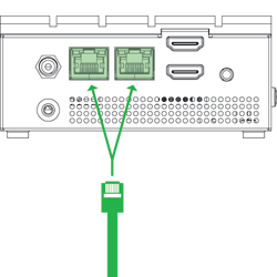
Proxies are not explicitly supported. If a proxy is implemented, it must be transparent to the gateway and downstream clients (i.e,. does not require any changes to client trusted certificates or configuration changes to use the proxy).
This port is only used for internet access. Do not connect access controllers to the Ethernet port.
- Connect the gateway to power.
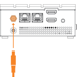
- Power on the gateway.
After being connected and powered on, the gateway communicates over the internet. All connections that the gateway establishes are outbound. The firewall does not need any ports opened for inbound connections.
Configure the Gateway
- In Elements, on the Devices page, add the gateway by selecting
 .
. - Enter a Name for the gateway.
- Enter the System ID.
- Select Save.
Status
Earlier models of the gateway have a single LED to indicate status of the gateway.
Single LED Behavior | Status |
|---|---|
Fast blinking white | Initialization |
Fast blinking red | No network connection or IP address |
Double blinking red | System registration service unreachable or no internet connection (IP address assigned) |
Blinking yellow | System registration service reachable, not connected to IoT |
Alternate blinking red, yellow | Lost connection to IoT Hub |
Steady green | Gateway operational |
LED off | Gateway powered off |
Later models of the gateway have three LEDs to indicate status of the gateway. These LEDs appear on the front of the gateway and are ordered, from left to right, red, orange, green.
Multiple LED Behavior | Status |
|---|---|
Blinking red, orange, and green | Initialization |
Blinking red | No network connection or IP address |
Steady red | System registration service unreachable |
Blinking orange | System registration service reachable, not connected to IoT |
Steady orange | Lost connection to IoT Hub |
Blinking red and orange | Gateway operational, pending association with customer |
Steady green | Gateway operational and associated with customer |
LED off | Gateway powered off |
Training video: Gateway LED Status Sequence
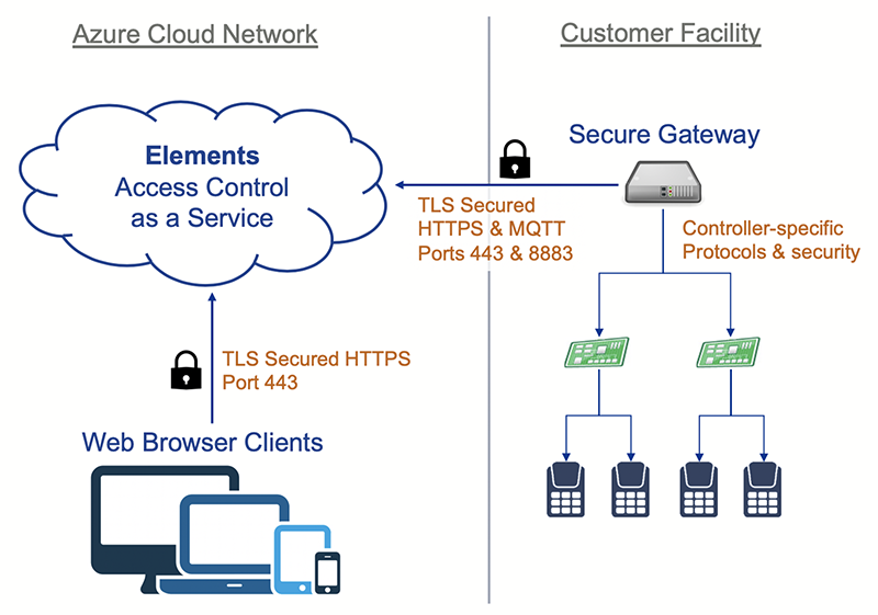
Architecture
Application and service connectivity information is provided so that the network may be secured.
High level architecture diagram
Security
Limit access to the network by enabling a firewall to secure ports and endpoints.
Communication for the Gateway
Outgoing: HTTPS (TCP 443) and MQTTS (TCP 8883)
US Endpoints:
deviceregistration.elementssecure.com:443
deviceregistration.elementslive.net:443
elements-prd-ioth.azure-devices.net:8883
elementsprdsa.blob.core.windows.net:443
gatewayfirmware.elementssecure.com:443
gatewayimages.elementssecure.com:443
Certain gateways shipped prior to January 2026 may need these additional endpoints to perform initial firmware update:
api.snapcraft.io:443
*.snapcraftcontent.com:443
Alternatively, if you are not able to add a wildcard endpoint, add the following individual endpoints:
storage.snapcraftcontent.com:443
canonical-lgw01.cdn.snapcraftcontent.com:443
canonical-lcy01.cdn.snapcraftcontent.com:443
canonical-lcy02.cdn.snapcraftcontent.com:443
canonical-bos01.cdn.snapcraftcontent.com:443
EU Endpoints:
deviceregistration.eu.elementssecure.com:443
elements-eu-prd-ioth.azure-devices.net:8883
elementseuprdsa.blob.core.windows.net:443
gatewayfirmware.eu.elementssecure.com:443
gatewayimages.eu.elementssecure.com:443
Certain gateways shipped prior to January 2026 may need these additional endpoints to perform initial firmware update:
api.snapcraft.io:443
*.snapcraftcontent.com:443
Alternatively, if you are not able to add a wildcard endpoint, add the following individual endpoints:
storage.snapcraftcontent.com:443
canonical-lgw01.cdn.snapcraftcontent.com:443
canonical-lcy01.cdn.snapcraftcontent.com:443
canonical-lcy02.cdn.snapcraftcontent.com:443
canonical-bos01.cdn.snapcraftcontent.com:443
Proxies are not explicitly supported. If a proxy is implemented, it must be transparent to the gateway.
Communication for Video
Communication with Milestone services from the Elements gateway is done on following ports:
Milestone OnvifServer Default Port: TCP 580
Milestone OnvifServer Default Port: TCP 554
Milestone Recording Server Default Port: TCP 7563
Milestone XProtect Configuration Server: TCP 80, 443
Configure the network infrastructure to allow connections to and from the above addresses on the following ports:
stun:global.stun.twilio.com
turn:global.turn.twilio.com
Port 3478 - Protocol: STUN, TURN UDP
Port 443 - Protocol: TURN TLS
Ports range 10000 - 60000 - Protocol: UDP/SRTP/SRTC