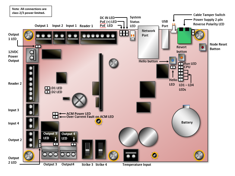
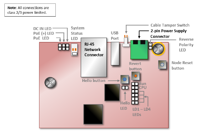
The options are listed below for supplying power to the MicroNode Plus for all peripheral devices, including strikes, readers, and other output devices such as Request to Exit (REX) devices, and alarm sounders.
Power Supply Options
Door Strike DC Voltage | MicroNode Plus Powered by: | MicroNode Plus Powered by: |
|---|---|---|
| External 12 VDC 3 Amp supply: 2000mA (24 watts) @12 DC | |
24 VDC | Running in NORMAL mode: Separate 24 VDC power supply required to power an external device. | |
Running in STRIKE mode:
| ||
12 VDC | Running in NORMAL mode: | |
In STRIKE mode, Outputs 3 and/or 4 can be configured as wet contact outputs that supply momentary power to the door strike(s) using at least 24 VDC and then drop to 12 VDC.
MicroNode Plus Interfaces
Button | Function |
|---|---|
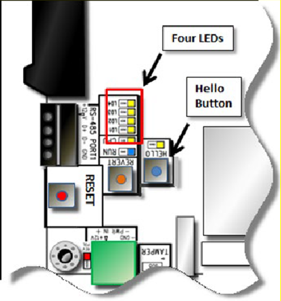
The Hello button is located near the Tamper Switch connector. | If a USB flash drive is plugged in to the node’s USB connector and the Hello button is pressed, the system will write its network configuration to or from the flash drive. This process takes about five seconds. |
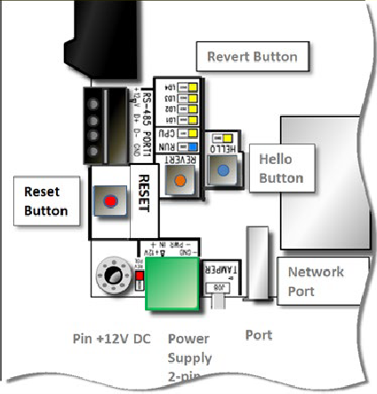
The Reset button is located near the Revert button and the green Power connector. | Pressing the Reset button resets the MicroNode Plus CPU, causing it to reboot. It will take approximately 25 seconds for the node to reboot and reconnect to the controller. When the node reconnects to the controller, the current system configuration is loaded onto the node. |
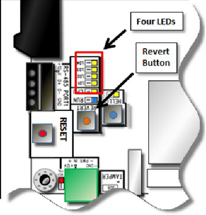
The Revert button is located near the green Power connector and the column of LEDs. | When you hold down the Revert button for at least 10 seconds, the four LEDs next to the button start to light up and then begin blinking on and off. Once all four buttons are blinking on and off at the same time, you can release the button and the revert will occur, returning the MicroNode Plus to its factory default settings:
|
Connect Power to the MicroNode Plus
This section describes how to connect a MicroNode Plus to an external power supply or to Power over Ethernet (PoE or PoE+).
WARNING: Observe static electricity precautions when handling and installing system components. These components can be damaged by static discharge.
Do not supply power to the boards until all connections are made. If you are using PoE or PoE+, make sure the far end of the network cable is not connected when you plug in to the network connector.
To connect an external 12V power supply to a MicroNode Plus:
Wire the power into the 2-pin power supply connector with a 12 VDC power source at no less than 3 Amps.
Connect the Ethernet cable (CAT-5, minimum) to the RJ-45 network connector.
With an external 12 VDC power supply as the power source, the total power available for all 12V output is 2000 mA (24 watts).
The wire from the external 12 VDC power supply should not be less than 18 AWG from a Safety Extra Low Voltage (SELV) source.
For UL listed products, a UL 294/UL 603 Class 2 power limited supply must be used. The power supply must be connected to a 24-hour un-switched outlet/source. Battery backup of this external power supply must be disconnected; standby power cannot be used with this product.
The RS-485 port has not been evaluated by UL and cannot be used for UL Listed products.
To connect MicroNode Plus to Power over Ethernet (PoE) or Power over Ethernet Plus (PoE+):
Connect the CAT-5 network cable to the RJ-45 network connector. See the diagram Connect 12 VDC power to MicroNode Plus.
When using PoE or PoE+, DC power is not required.
The MicroNode Plus requires that the PSE to conform to the IEEE 802.3af-2003 (57VDC at a maximum of 400mA) standard or the IEEE 802.3at - 2009 (57VDC at a maximum of 800mA ) standard.
With PoE (44-57 VDC 275mA) as the power source, the total power available for all 12V output is 500mA (6 watts).
With PoE+ (50-57 VDC 450mA) as the power source, the total power available for all 12V output is 1000mA (12 watts).
Neither PoE nor the Ethernet connector (CAT-5, minimum) has been evaluated by UL and neither can be used for UL Listed products.
© 2026 Honeywell International Inc. All Rights Reserved.
