Once power is connected to the MicroNode Plus, you can wire the following door hardware:
24 VDC door strikes. These can be powered either by MicroNode Plus or by an external power supply. See Power supply options for more information.
12 VDC door strikes or magnetic locks. These must be powered by an external power supply.
Two (2) readers to be powered by MicroNode Plus.
Up to four (4) input devices. Two of these can be 12V devices, such as Request to Exit devices and alarm sounders that are powered by MicroNode Plus.
IMPORTANT: Magnetic locks cannot be directly powered by MicroNode Plus.
With an external 12 VDC 3A power supply as the power source for MicroNode Plus, the total power available for all output is 12 VDC at 1100 mA (13 watts). For UL Listed products, a UL 294/UL 603 power limited supply must be used. The power supply must be connected to a 24 hour un-switched outlet/source. Battery backup of this external power supply must be disconnected; standby power cannot be used with this product.
With PoE as the power source for MicroNode Plus, the total power available for all external devices is 500 mA (6 watts).
Neither PoE nor the CAT5 Ethernet connector has been evaluated by UL.
Options for wiring door strikes and magnetic locks are as follows:
Wet contact: You can connect a 24 VDC door strike to a wet contact output so the strike can be powered by MicroNode Plus.
IMPORTANT: Current power limits apply. The total 12 VDC power available for all outputs depends on how the MicroNode Plus is powered:
When power is supplied by PoE (44-57 VDC 275mA): 500mA (6 watts) @12 VDC.
When power is supplied by PoE+ (50-57 VDC 450mA): 1000mA (12 watts) @12 VDC.
When power is supplied by an external 12 VDC 3A supply: 2000mA (24 watts) @12 VDC.
Dry contact: You can connect a 12V or 24V door strike or magnetic lock to a dry contact output so that the strike can be powered by an external power supply.
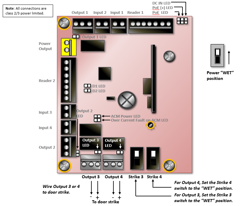
Wire Strikes Powered by MicroNode Plus (Wet Contact)
Outputs 3 and 4 on MicroNode Plus can be configured as WET and used to supply momentary power to 24 VDC door strikes.
To wire a door strike to be powered by MicroNode Plus:
Wire the door strike to Output Connector 3 or 4.
Set the strike switch for that output to the WET position, as shown for Output 3 in the following diagram.
This allows the capacitor near the switch to provide power to flip the strike.
WARNING: Polarity shown must be observed if using a diode to clamp the kickback voltage from the strikes. We recommend the use of a diode, varistor, or transient voltage suppressor (TVS).
Wire Strikes or Magnetic Locks Powered Externally (Dry Contact)
Outputs that require external power need to have diodes and varistors installed to protect the output circuits. Failure to properly install the diodes and varistors may reduce the relay contact life and lead to premature failure of electrical components.
All outputs are dry-contact. Dry contacts are rated 24 VCD/AV, 2A for resistive and inductive loads.
Install diodes and varistors for outputs powered externally
Power down the MicroNode Plus by removing power from the power connector and battery connector.
Make sure you are grounded, and then pull the wiring through a knockout in the cabinet.
Note: The wire specification is twisted, shielded 22 AWG Belden #9462 or equivalent. The maximum distance is 2000 feet (610 meters). See Practical guidelines for effective shielding for more information.Refer to the output device manual to determine if the device is normally energized or normally not energized, and if it is DC or AC powered.
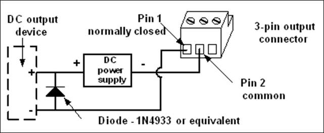
Connect the output wiring to the 3-pin output connector:
Pin 1 is normally closed (NC).
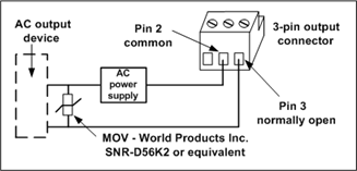
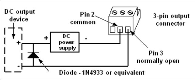
Pin 2 is common.
Pin 3 is normally open (NO).
Be sure there is power to the MicroNode Plus, and then plug the connector into an output position on an access control blade or an output blade. These connectors are polarized and can only be inserted one way.
If the output device is DC powered and normally closed, install a diode (1N4933-1 A, 50 V, Fast Recovery Diode or equivalent) in the circuit:
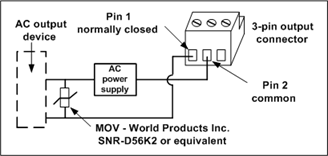
If the output device is AC powered and normally open, install a varistor (40 VAC, 56 VDC, 10 A Surge, Radial Leaded Varistor or equivalent such as World Products Inc. SNR-D56K2) in the circuit:
If the output is DC powered and normally open, install a diode (1N4933- 1 A, 50 V, Fast Recovery Diode or equivalent) in the circuit:
If the output device is AC powered and normally closed, install a varistor (40 VAC, 56 VDC, 10 A Surge, Radial Leaded Varistor or equivalent, such as World Products Inc. SNR-D56K2) in the circuit:
Connect a Door Strike or Magnetic Lock to an External Power Supply
Any output can be used to power a 12V or 24V door strike or magnetic lock (maximum electrical rating: 2.5 Amps with an inductive load). If Output 3 or 4 is selected, the strike switch must be set to the DRY position, as shown for Output 3 in the following diagram, for it to use an external power source.
To connect a door strike or magnetic lock to an external power supply:
Connect a wire (minimum 20 AWG) from the negative (-) side of a 12 VDC external power supply to the common pin of the chosen output connector.
Connect a wire from the normally open (NO) pin of the output to one side of the strike or magnetic lock.
Connect a wire from the other side of the strike or magnetic lock to the positive (+) side of the 12 VDC external power supply.
Connect 12 VDC door strike or magnetic lock to an external power supply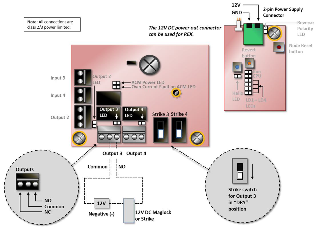
Wire Other Output Devices
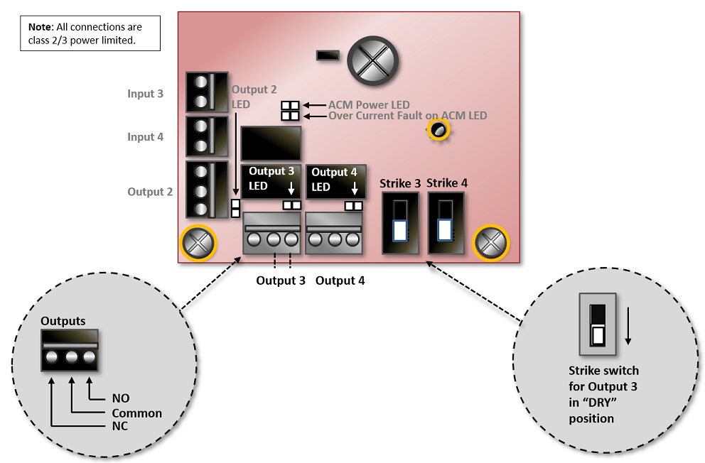
To wire other output devices that do not require power from MicroNode Plus, you can use any output. If Output 1 or Output 2 is selected, you can simply wire the device’s state wires to the output connector. If Output 3 or 4 is selected, you must set the Strike 3 or Strike 4 switch to DRY to receive external power.
WARNING: Outputs that require external power need to have diodes and varistors installed to protect the output circuits. Failure to properly install the diodes and varistors may reduce the relay contact life and lead to premature failure of electrical components. See Install diodes and varistors for outputs powered externally for details.
To wire other output devices:
Connect one wire from the output device to the common pin of the output connector.
Connect the other wire from the output device to either the normally open (NO) or normally closed (NC) pin of the output connector.
WARNING: If Output 3 or 4 is selected you must set the strike switch to the DRY position. Otherwise, power will be delivered to the output device. The following diagram shows Output 3 and its strike switch, Strike 3 set to DRY.
The MicroNode Plus supports four relay outputs. Relay output connectors are 3-pin. Both normally-open circuit devices and normally-closed circuit devices are supported. The relay outputs support any output device that operates on the following maximum electrical ratings: 30 volts, 2.5 Amps DC or AC, inductive, or 3.0 Amps non-inductive.
Wire Input Devices
This section describes how to:
Wire input devices, such as Request to Exit (REX) devices.
Wire and power readers.
MicroNode Plus - Power Limits
When wiring input devices that require power from MicroNode Plus, keep in mind that the total current consumption cannot exceed:
500mA (6 watts) @12 VDC when power is supplied to MicroNode Plus by PoE (44-57 VDC 275mA)
1000mA (12 watts) @12 VDC when power is supplied to MicroNode Plus by PoE+ (50-57 VDC 450mA)
Wire Input Devices Requiring Power from MicroNode Plus
There are connectors for two (2) input devices, but more may be supported as long as the total current consumption does not exceed the power limits given above.
These inputs can support a wide variety of input supervision types. To configure inputs and input supervision types, log in to Elements.
2000mA (24 watts) when power is supplied to MicroNode Plus by an external 12 VDC @ 3A power supply.
To wire and power an input device:
Wire the input device to the pair of 12V/ground connectors on the 2-pin Power Supply connector.
Connect the input wires to the Pin 1 and Pin 2 connectors on Input 3.
Power supply and input connectors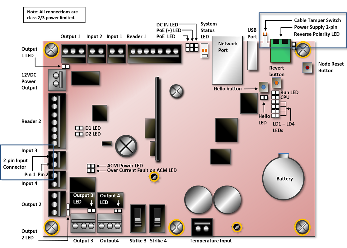
Wire Input Devices Not Requiring Power from MicroNode Plus
These inputs can support a wide variety of input supervision types. To configure inputs and input supervision types sign in to Elements.
To wire an input device that does not require power from MicroNode Plus: Connect the input wires to the Pin 1 and Pin 2 connectors on Input 3, shown in Power supply and input connectors above.
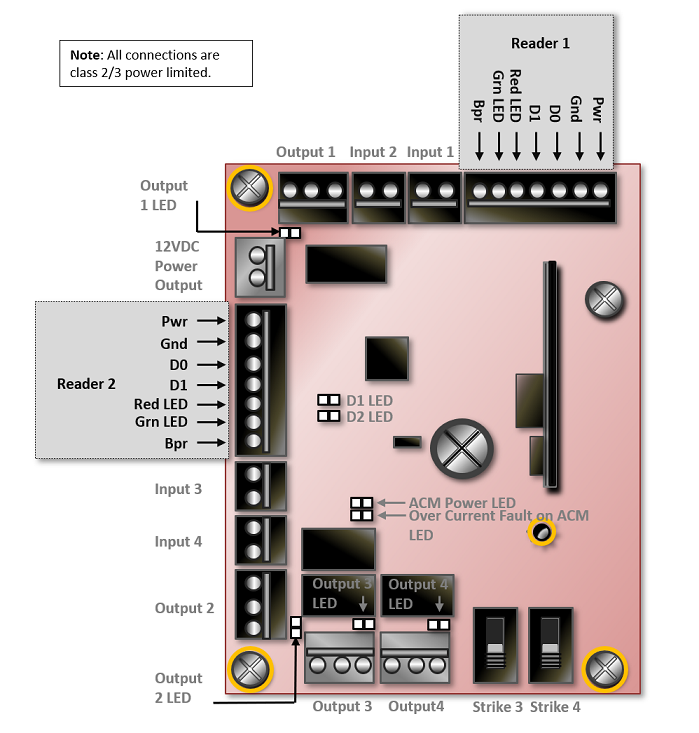
Wire and Power Readers
MicroNode Plus can power up to two (2) readers.
To wire and power a reader: Connect the reader wires to one of the two 7-pin reader connectors:
Practical Guidelines for Effective Shielding
When wiring readers, inputs, outputs, and temperature sensors, follow the guidelines below for effective cable shielding:
Make sure your cable has sufficient shielding for the application’s needs. In moderately noisy environments, a foil alone may provide adequate protection. In noisier environments, consider braids or foil-braid combinations.
Use a cable suited to the application. Cables that experience repeated flexing should generally use a spirally wrapped shield rather than a braid. Avoid foil-only shielding on flex cables, because continuous flexing can tear the foil.
Make sure the equipment to which the cable is connected is properly grounded. Use an earth ground wherever possible and check the connection between the ground point and the equipment. Eliminating noise depends on a low impedance path to ground.
Most connector designs allow full 360° termination of the shield. Make sure the connector offers shielding effectiveness equal to that of the cable. For example, many common connectors are offered with metal-coated plastic, cast zinc, or aluminum backshells.
Ground the cable at one end. This eliminates the potential for noise-inducing ground loops.
Connect Power
WARNING: Do not supply power to MicroNode Plus until all connections are made. If you are using PoE or PoE+, make sure that the far end of the network cable is not connected when you plug in to the network connector.
To apply power:
Supply power to the MicroNode Plus unit by powering the external 12 VDC power supply or by connecting the far end of the network cable to a PoE or PoE+ switch or mid-span power injector.
PoE and PoE+ switches and mid-span power injectors have not been evaluated by UL and cannot be connected to UL Listed products.