The LNL-1100 Board
The LNL-1100 processor provides a solution to the host system integrator for sensor monitoring and output control. The LNL-1100 has 16 non-supervised or supervised inputs and two (2) form-C contact relays for load switching. In addition, two (2) digital inputs are used for cabinet tamper and power fault status monitoring. The processor requires 12 to 24 VDC for power.

The LNL-1100 Board Callouts
Callout | Description |
|---|---|
1 | Inputs |
2 | Serial I/O communication port, RS-485 |
3 | Power in 12-24 VDC |
4 | Earth ground (connection not required) |
5 | Eight (8) mounting holes (Ø0.16 [Ø3.96]) |
6 | Outputs |
7 | Status LEDs |
8 | DIP switches |
9 | Inputs |
10 | Input Status LEDs |
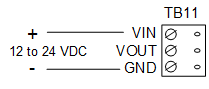
Supplying Power to the LNL-1100
The LNL-1100 accepts 12 to 24 VDC for power. Locate power source as close to the unit as possible. Connect power with minimum of 18AWG wires.
Observe POLARITY on VIN!
The VOUT terminal on TB11 is the same as VIN.
Communication Wiring
The LNL-1100 communicates to an intelligent controller (for example, the LNL-3300) via a 2-wire RS-485 interface. The interface allows multi-drop communication on a single bus of up to 4000 feet (1219 m). Shielded cable of 24 AWG with characteristic impedance of 120 ohm is specified for the RS-485 interface. See Specifications section.
Install RS-485 termination jumper, J3, on the interface boards at each end of the communication line, only.
2-Wire RS-485
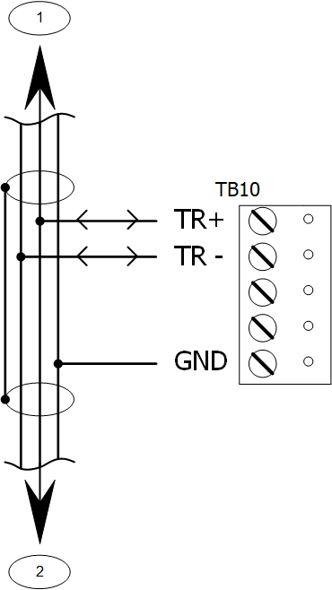
Communication Wiring Callouts
Callout | Description |
|---|---|
1 | To all other devices on the bus |
2 | To all other devices on the bus |
ONLY 2-WIRE RS-485 IS SUPPORTED. | |
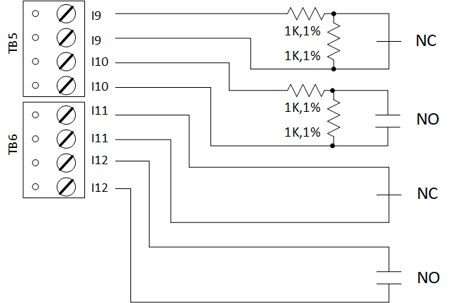
Alarm Inputs Wiring
Inputs 1 to 16 can be configured to use or not use End Of Line (EOL) resistors and to use normally open or normally closed contacts. Input CT and input BA are used for monitoring cabinet tamper and power failure, respectively. These two (2) inputs are for contact closure monitoring only, and do not use EOL resistors.
Input configuration is set via the host software.
Relay Outputs
Two (2) form-C contact relays are provided for controlling door strikes or other devices. Load switching can cause abnormal contact wear and premature contact failure. Switching of inductive loads (strike) also causes EMI (electromagnetic interference) which may interfere with normal operation of other equipment. To minimize premature contact failure and to increase system reliability, a contact protection circuit must be used. The following two (2) circuits are recommended. Locate the protection circuit as close to the load as possible (within 12 inches [30cm]) as the effectiveness of the circuit will decrease if it is located farther away.
Use sufficiently large gauge of wires for the load current as to avoid excessive voltage drop.
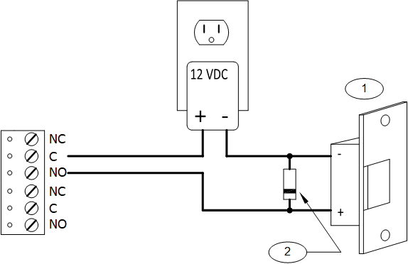
Diode Selection: Diode current rating: 1x strike current. Diode breakdown voltage: 4x strike voltage. For 12 VDC or 24 VDC strike, diode 1N4002 (100V/1A) typical.
Relay Outputs Callouts
Callout | Description |
|---|---|
1 | DC strike |
2 | Diode |
DIP Switch and Jumper Usage
Switches 1 to 5 select the device address. Switches 6 and 7 select the communication baud rate. Switch 8 enables encrypted communication. All other configuration settings are set via host software.
DIP switch(es) | Used to configure |
|---|---|
1, 2, 3, 4, 5 | Device communication address (0-31) |
6, 7 | Communication baud rate |
8 | Downstream encryption (available with OnGuard® 2009 or later) |
Device Address
Address | DIP switch | ||||
|---|---|---|---|---|---|
5: | 4: | 3: | 2: | 1: | |
0 | off | off | off | off | off |
1 | off | off | off | off | ON |
2 | off | off | off | ON | off |
3 | off | off | off | ON | ON |
4 | off | off | ON | off | off |
5 | off | off | ON | off | ON |
6 | off | off | ON | ON | off |
7 | off | off | ON | ON | ON |
8 | off | ON | off | off | off |
9 | off | ON | off | off | ON |
10 | off | ON | off | ON | off |
11 | off | ON | off | ON | ON |
12 | off | ON | ON | off | off |
13 | off | ON | ON | off | ON |
14 | off | ON | ON | ON | off |
15 | off | ON | ON | ON | ON |
16 | ON | off | off | off | off |
17 | ON | off | off | off | ON |
18 | ON | off | off | ON | off |
19 | ON | off | off | ON | ON |
20 | ON | off | ON | off | off |
21 | ON | off | ON | off | ON |
22 | ON | off | ON | ON | off |
23 | ON | off | ON | ON | ON |
24 | ON | ON | off | off | off |
25 | ON | ON | off | off | ON |
26 | ON | ON | off | ON | off |
27 | ON | ON | off | ON | ON |
28 | ON | ON | ON | off | off |
29 | ON | ON | ON | off | ON |
30 | ON | ON | ON | ON | off |
31 | ON | ON | ON | ON | ON |
Communication Baud Rate
Baud rate | DIP switch 6: | DIP switch 7: |
|---|---|---|
38,400 bps | ON | ON |
19,200 bps | off | ON |
9600 bps | ON | off |
115,200 bps | off | off |
Bus Encryption
Bus communications | DIP switch 8: | DIP switch 8: |
|---|---|---|
Encryption is not required | off | Normal operation |
Encryption is required | ON | Not allowed |
Jumpers
Jumper | Description |
|---|---|
J3 | RS-485 termination; install in first and last units, only |
All other jumpers are factory use, only.
Status LEDs
Power-up: All LEDs OFF.
Initialization: Once power is applied, initialization of the module begins.
When initialization is completed, LEDs 1-16, CT, BA, A and B are briefly sequenced ON then OFF.
Run time: After the above sequence, the LEDs have the following meanings:
A LED: Heartbeat and On-Line Status:
- Off-line: 1 second rate, 20% ON
- On-line:
- Non-encrypted communication: 1 second rate, 80% ON
- Encrypted communication: 0.1 sec ON, 0.1 sec OFF, 0.1 sec ON, 0.1 sec OFF, 0.1 sec ON, 0.1 sec OFF, 0.1 sec ON, 0.3 sec OFF
A LED: Error Indication:
Waiting for application firmware to be downloaded: 0.1 sec ON, 0.1 sec OFF.
B LED: Serial I/O Communication Port Status:
Indicates communication activity on the serial I/O communication port:
1 LED: Input Status: 1
2 LED: Input Status: 2
3 LED: Input Status: 3
4 LED: Input Status: 4
5 LED: Input Status: 5
6 LED: Input Status: 6
7 LED: Input Status: 7
8 LED: Input Status: 8
9 LED: Input Status: 9
10 LED: Input Status: 10
11 LED: Input Status: 11
12 LED: Input Status: 12
13 LED: Input Status: 13
14 LED: Input Status: 14
15 LED: Input Status: 15
16 LED: Input Status: 16
CT: Cabinet Tamper
BA: Power Fault
Input in the inactive state: OFF (briefly flashes ON every 3 seconds)
Input in the active state: ON (briefly flashes OFF every 3 seconds)
Input in a fault state: Rapid Flash
LED K1 and K2: Illuminates when output relay RLY 1 (K1) or RLY 2 (K2) is energized.
Specifications
The LNL-1100 is for use in low voltage, class 2 circuit, only. These specifications are subject to change without notice.
Primary power: 12 to 24 VDC ± 10%, 350 mA maximum
Outputs: Two (2) Form-C relays:
- Normally Open contact (NO) contact: 5 A @ 30 VDC resistive
- Normally Closed contact (NC) contact: 3 A @ 30 VDC resistive
Inputs:
- 16 unsupervised/supervised, standard EOL: 1k/1k ohm, 1%, 1/4 watt
- Two (2) unsupervised, dedicated for cabinet tamper and UPS fault monitoring
Communication: RS-485, 2-wire: 9600, 19200, 38400, or 115200 bps
Cable requirements:
- Power: 18 AWG, 1 twisted pair
- RS-485: 24 AWG, 120 ohm impedance, twisted pair with drain wire and shield, 4000 feet (1219 m) maximum
- Alarm inputs: 1 twisted pair, 30 ohms maximum
- Output: As required for the load
Mechanical:
- Dimension: 6 x 8 x 1 in. (152 x 203 x 25.4 mm)
- Weight: 9 oz. (250 g) nominal
Environment:
- Temperature: -55°C to +85°C storage
- 0°C to +70°C operating
- Humidity: 5% to 95% RHNC
These specifications are subject to change without notice.
Regulatory Information
FCC Compliance
This device complies with part 15 of the FCC Rules. Operation is subject to the following two conditions: (1) This device may not cause harmful interference, and (2) this device must accept any interference received, including interference that may cause undesired operation.
Liability
It is expressly understood and agreed that the interface should only be used to control exits from areas where an alternative method for exit is available. This product is not intended for, nor is rated for operation in life-critical control applications. LenelS2 is not liable under any circumstances for loss or damage caused by or partially caused by the misapplication or malfunction of the product. LenelS2’s liability does not extend beyond the purchase price of the product.
Certifications
For certification information, refer to the hardware documentation for the host application.
Product Warnings and Disclaimers
THESE PRODUCTS ARE INTENDED FOR SALE TO, AND INSTALLATION BY, AN EXPERIENCED SECURITY PROFESSIONAL. LENELS2 CANNOT PROVIDE ANY ASSURANCE THAT ANY PERSON OR ENTITY BUYING ITS PRODUCTS, INCLUDING ANY “AUTHORIZED DEALER”, IS PROPERLY TRAINED OR EXPERIENCED TO CORRECTLY INSTALL SECURITY RELATED PRODUCTS. FOR MORE INFORMATION ON PRODUCT WARNINGS AND DISCLAIMERS, SEE THE "LENELS2 PRODUCT WARNINGS AND DISCLAIMERS" KNOWLEDGE BASE ARTICLE IN THE LENELS2 KNOWLEDGE BASE. THIS INFORMATION IS SUBJECT TO CHANGE WITHOUT NOTICE.