The Elements Video Recorder facilitates communication between the cloud-based security system and on-site video devices.
Download the Video Recorder Quick Start Guide PDF.
Download the full Video Recorder Installation Guide PDF.
Contents
The following items are included in the box with each video recorder.
One (1) recorder unit
One (1) sticker label containing the System ID
One (1) power cord
Video Recorder Installation
Before installing the recorder, make note of its System ID. The System ID is printed on a label affixed to the recorder.
Connect the Recorder
Connect the recorder to an internet-accessible network. For initial configuration, use the Ethernet port on the right on the back of the recorder. After configuration, either Ethernet port may be used.
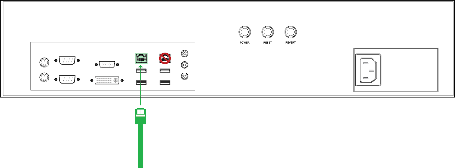
The recorder depends on the network being configured for DHCP. If a static IP address is needed for the recorder, it must be configured using MAC address mapping on the DHCP server.
Proxy configuration is not supported.
Connect the recorder to power.
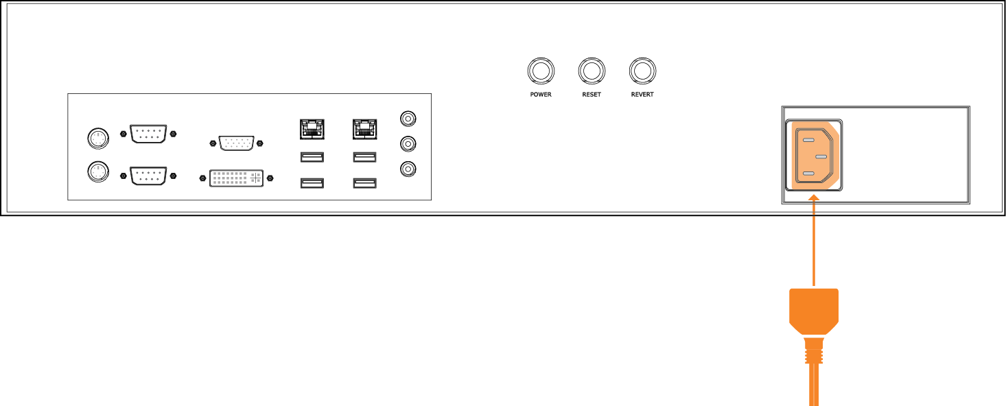
Power on the recorder.
After being connected and powered on, the recorder communicates over the internet. All connections that the recorder establishes are outbound. The firewall does not need any ports opened for inbound connections.
Power and Reset
The recorder has three buttons on the back panel:
Reset - Press this button to restart the system.
Power - Press this button momentarily to power on the system. When the system is up and running, press this button momentarily to initiate an orderly system shutdown and power down. Hold this button down for three seconds to initiate a hard system shutdown and power down.
Revert - This button is not used.
Configure the Recorder
In Elements, on the Devices page, add the recorder by selecting Add > Recorder.
Enter a Name for the recorder.
Enter the Video Retention period in days. This is the maximum number of days that video will be stored on the recorder.
Enter the System ID of the recorder.
Select the Time Zone for the recorder.
Select Save.
Status
A single LED installed in a USB port of the recorder indicates the system status.
LED Behavior | Status |
|---|---|
Fast blinking white | Initialization |
Fast blinking red | No network connection or IP address |
Double blinking red | System registration service unreachable |
Blinking yellow | System registration service reachable, not connected to IoT |
Alternate blinking red, yellow | Lost connection to IoT Hub |
Steady green | Recorder operational |
LED off | Recorder powered off |
Security
Limit access to the network by enabling a firewall to secure ports and endpoints.
Communication for the Gateway
Outgoing: HTTPS (TCP 443) and MQTTS (TCP 8883)
US Endpoints:
deviceregistration.elementssecure.com:443
deviceregistration.elementslive.net:443
elements-prd-ioth.azure-devices.net:8883
elementsprdsa.blob.core.windows.net:443
gatewayfirmware.elementssecure.com:443
gatewayimages.elementssecure.com:443
api.snapcraft.io:443
*.snapcraftcontent.com:443
Alternatively, if you are not able to add a wildcard endpoint, add the following individual endpoints:
storage.snapcraftcontent.com:443
canonical-lgw01.cdn.snapcraftcontent.com:443
canonical-lcy01.cdn.snapcraftcontent.com:443
canonical-lcy02.cdn.snapcraftcontent.com:443
canonical-bos01.cdn.snapcraftcontent.com:443
EU Endpoints:
deviceregistration.eu.elementssecure.com:443
elements-eu-prd-ioth.azure-devices.net:8883
elementseuprdsa.blob.core.windows.net:443
gatewayfirmware.eu.elementssecure.com:443
gatewayimages.eu.elementssecure.com:443
api.snapcraft.io:443
*.snapcraftcontent.com:443
Alternatively, if you are not able to add a wildcard endpoint, add the following individual endpoints:
storage.snapcraftcontent.com:443
canonical-lgw01.cdn.snapcraftcontent.com:443
canonical-lcy01.cdn.snapcraftcontent.com:443
canonical-lcy02.cdn.snapcraftcontent.com:443
canonical-bos01.cdn.snapcraftcontent.com:443
Proxies are not explicitly supported. If a proxy is implemented, it must be transparent to the gateway.
Communication for Video
Configure the network infrastructure to allow connections to and from the addresses on the following ports:
stun:global.stun.twilio.com
turn:global.turn.twilio.com
Port 3478 - Protocol: STUN, TURN UDP
Port 443 - Protocol: TURN TLS
Ports range 10000 - 60000 - Protocol: UDP/SRTP/SRTC
© 2026 Honeywell International Inc. All Rights Reserved.