Wire the reader in accordance with local codes, authoritative jurisdictions, and the National Electrical Code (ANSI/NFPA70).
Wiring Recommendations
The OSDP configuration is recommended because it is the most secure. Use the reader wiring diagrams and LED functionality described for each reader type.
Cable Length
Up to 492 feet (150 m) of cable length may be used.
Cable Type
Wiegand: BELDEN 953x (or UL equivalent).
RS-485: BELDEN 9502 (or UL equivalent).
Wire Size
The wire size should be 24 AWG or larger.
Shielding
Connect the reader ground wire to the cable shielding, and shield wires at the micro-controller. All cables and wiring must be UL listed and suitable for use.
OSDP Wiring
OSDP Reader Wiring Diagram
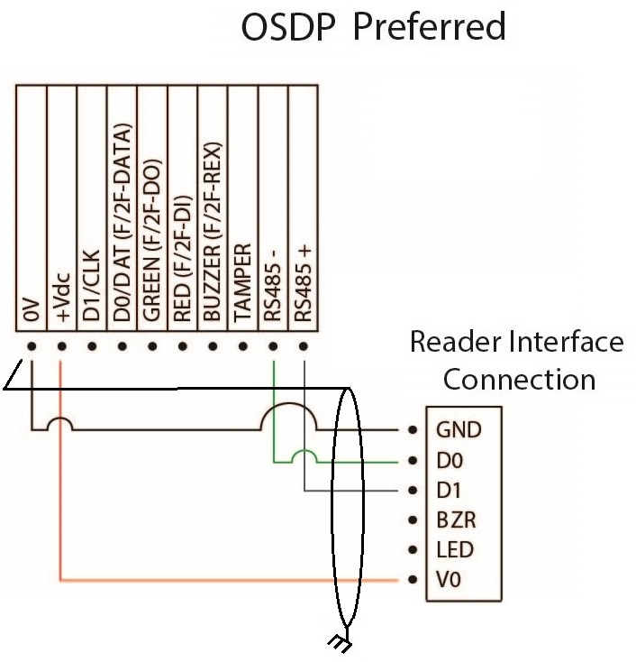
OSDP LED Functionality
Card Reader Modes | OSDP | ||
|---|---|---|---|
1 | Credential and PIN | 1 | Blinking red to blinking yellow |
2 | Credential only | 2 | Blinking red |
3 | Credential or PIN | 3 | Blinking red |
3b | PIN only | 3b | Blinking red to solid yellow |
4 | Cipher lock emulation | 4 | Blinking red |
5 | Facility code mode | 5 | Blinking red |
6 | Locked | 6 | Solid red |
7 | Unlocked | 7 | Solid green |
8 | Default state when powered online | 8 | Alternating red and blue |
9 | Access granted | 9 | Blinking green (2 beeps) |
10 | Access denied | 10 | Solid red (3 beeps) |
11 | Waiting for PIN | 11 | Blinking yellow |
12 | Waiting for second credential | 12 | Blinking green |
Wiegand Wiring
Wiegand 2-wire Reader to Interface Wiring Diagram
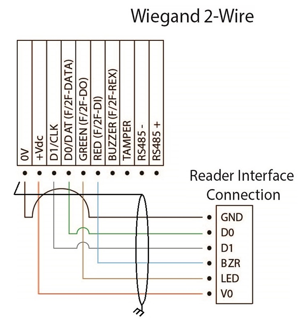
Wiegand 2-Wire LED Functionality
Card Reader Modes | Wiegand | ||
|---|---|---|---|
1 | Credential and PIN | 1 | Alternating red and blue |
2 | Credential only | 2 | Alternating red and blue |
3 | Credential or PIN | 3 | Alternating red and blue |
3b | PIN only | 3b | Red and blue to solid yellow |
4 | Cipher lock emulation | 4 | Alternating red and blue |
5 | Facility code mode | 5 | Alternating red and blue |
6 | Locked | 6 | Solid red |
7 | Unlocked | 7 | Solid green |
8 | Default state when powered online | 8 | Alternating red and blue |
9 | Access granted | 9 | Alternating green and blue |
10 | Access denied | 10 | Solid red |
11 | Waiting for PIN | 11 | Blinking yellow |
12 | Waiting for second credential | 12 | Alternating green and blue |
Wiegand 1-wire Reader to Interface Wiring Diagram
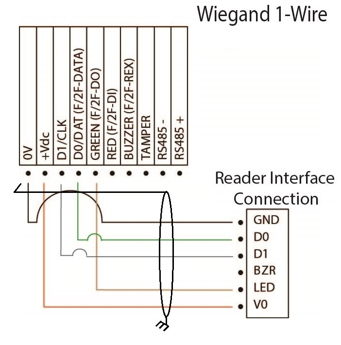
Wiegand 1-Wire LED Functionality
Card Reader Modes | Wiegand | ||
|---|---|---|---|
1 | Credential and PIN | 1 | Solid blue |
2 | Credential only | 2 | Solid blue |
3 | Credential or PIN | 3 | Solid blue |
3b | PIN only | 3b | |
4 | Cipher lock emulation | 4 | Solid blue |
5 | Facility code mode | 5 | Solid blue |
6 | Locked | 6 | Solid blue |
7 | Unlocked | 7 | Solid green |
8 | Default state when powered online | 8 | Red/green/blue then solid blue |
9 | Access granted | 9 | Alternating green and blue |
10 | Access denied | 10 | Blue (flashes for a second) |
11 | Waiting for PIN | 11 | Alternating blue and yellow |
12 | Waiting for second credential | 12 | Alternating green and blue |