Power on the AH40 IP Hub or AH30 Hub, and Aperio wireless locks.
Connect the USB dongle to the computer with the configuration software.
Run the Aperio programming application.
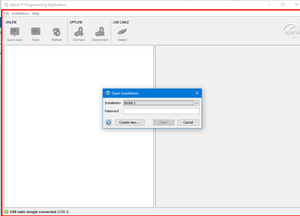
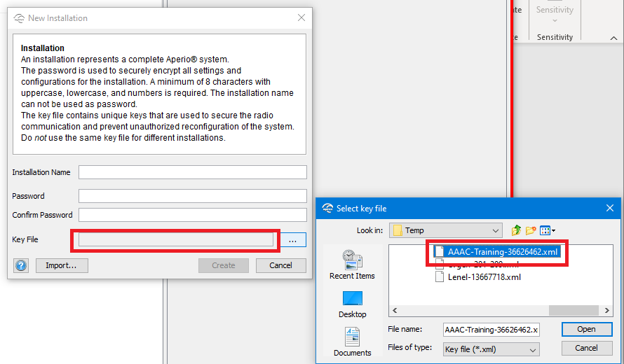
- Create the new installation:
- Enter the Installation Name.
- Enter and confirm a Password.
- To select the Key File, browse to the folder where the key file is stored, and then choose Open to select it.
- If the installation is already created, select Quick scan to search for communication hubs within range. The hubs are identified by the last 3 bytes of their MAC address.
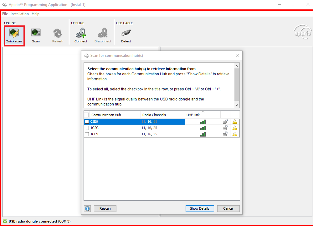
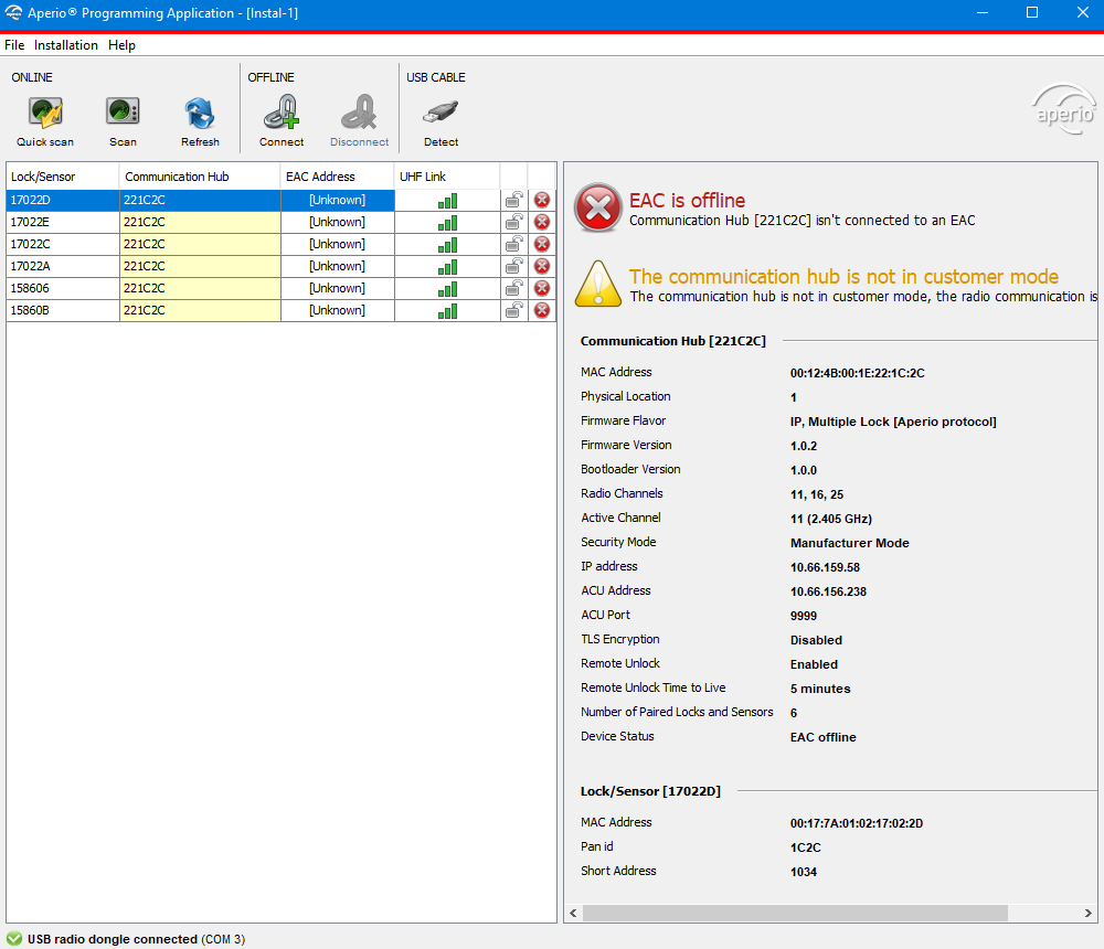
- Select the hub, and then select Show Details. The locks which are already added to the selected hub are listed:
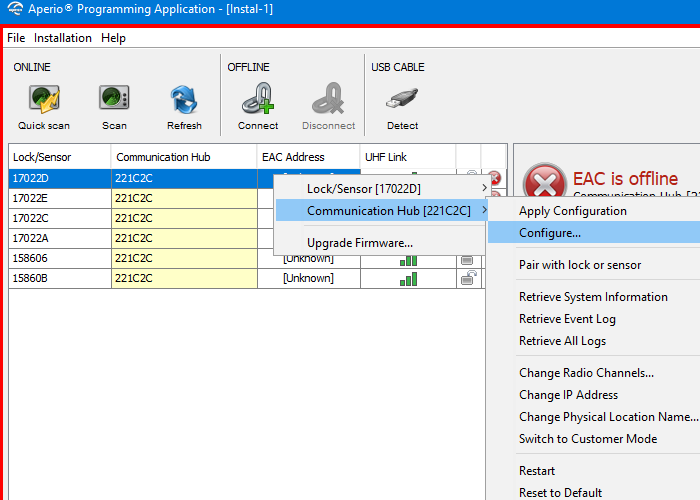
- Right-click on a record for the hub, and then select Communication hub > Configure.
The configuration wizard walks you through a series of screens:- Security Mode Setting: Manufacturer or Customer Mode. During configuration, the locks and hub should all be in Manufacturer Mode.
- Electronic Access Controller Settings:
- EAC Addressing Mode: This is a method of addressing hubs in Elements; either one-by-one (Legacy) or according to the Normal address offset.
- Lock Access Decision Timeout: 2 seconds by default.
- Remote Unlock: 5 minutes by default.
- EAC Credential Settings: Disabled for RFID by default.
- Network Settings: The mask and gateway for the network environment of the IP hub.
- ACU Settings (AH40 IP Hub Locks only): The IP address and communication port (9999 by default) of the LNL-M or LNL-X series controller that communicates with the AH40 IP hub. TLS Encryption should match what is configured for the controller.
The Aperio Programming Application uses the term ACU that refers to the Access Control Unit (LNL-X or LNL-M series controller) the Aperio AH40 IP hub needs to communicate with. There are three important settings here: The LNL-M or X series controller's IP Address, the Port to communicate to the controller, and if TLS encryption should be used for communications. These same parameters need to be entered into the access controller configuration, so make note of them.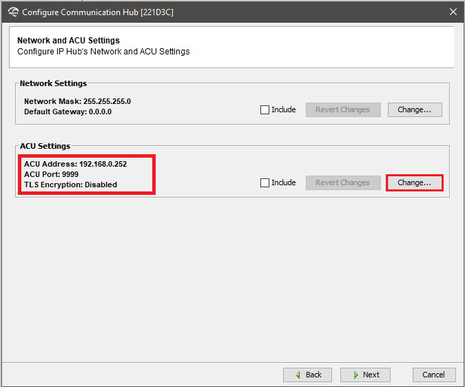
In the ACU Settings section, select Change to open the ACU Settings dialog. If TLS encryption should be used for communication, select Enable TLS. Select OK. (Refer to TLS Setup for the Hubs for instructions.)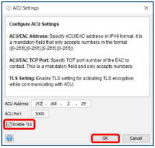
To verify the IP address of the hub that will be applied in Elements, select Communication Hub > Change IP Address.
Radio Channels: Available from 11 to 26. (11,16,25 is selected by default.).
If several hubs in the area are using radio channel, you may want to choose another channel to prevent signal disturbances.
- Status Report Interval: 1 hour by default. For more information, see Status Report Interval for the hubs.
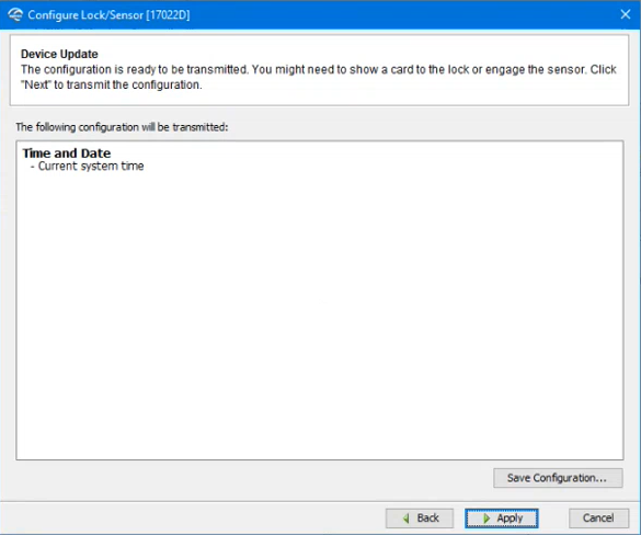
- Device Update: Select Apply to transmit the configuration to the device. If you save a configuration, you can apply it to other devices. This function is available on both the Lock/Sensor menu and the Communication Hub menu and will only download settings that apply to the hardware selected. Select Save Configuration to open the Save Configuration dialog to save the configuration in local storage for later use.
- After the IP hub is configured, add a new wireless lock and assign it to the hub:
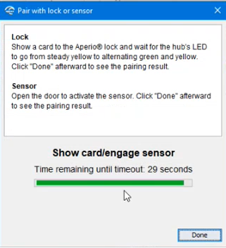
- Right-click on the IP hub, and then select Communication Hub > Pair with lock or sensor.
- Present a valid badge to the lock being paired.
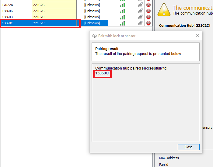
- The new lock will be automatically added to the configuration as seen in the list of locks.
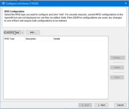
- Right-click on the new lock, and then select Lock/Sensor > Configure. A series of screens are shown for configuring the lock:
- RFID Configuration: Select Next to accept the default values:
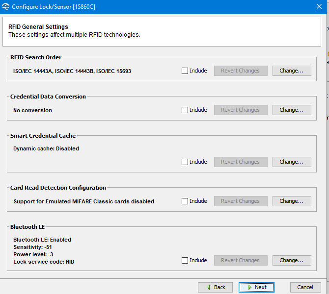
- RFID General Settings: Select Next to accept the default values:
- Escape and Return Configuration (Lock): This function allows the lock to remain unlocked a certain time after the door has been opened from the inside.
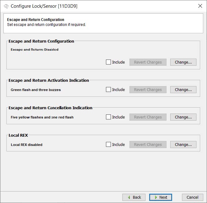
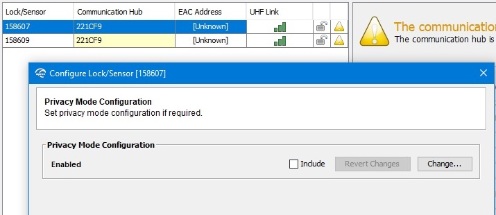
The Privacy mode function provides a method for an occupant of a room to lock the door and change access rights to the room. The privacy mode function can be enabled on locks equipped with privacy mode button or a monitored deadbolt. - Privacy Mode Configuration: The privacy mode corresponds to the Privacy mode setting when adding or modifying a lock. (See Add an Aperio Lock.)
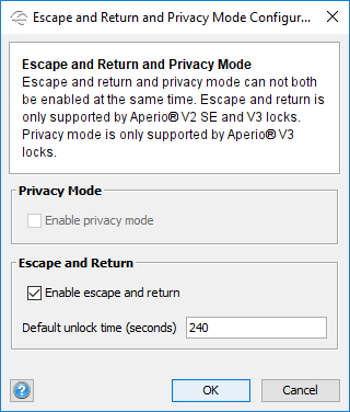
Escape and Return and Privacy Mode configuration: The user interface depends on the version of the lock and the lock's firmware:
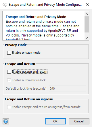
Privacy Mode: Enables the possibility to use the privacy mode button or deadbolt, to change access rights to the room. If the lock is offline, only override credentials can open the lock. This function is supported by V3 locks only.
Escape and Return: Activate the function to allow the lock to remain unlocked after the door has been opened from the inside.
Note: Escape and Return and Privacy Mode cannot be enabled at the same time.
Note: If Local REX is enabled, Escape and Return is disabled. If Escape and Return is enabled, Local REX is disabled.
Enable automatic re-lock: Activate the function to automatically re-lock the lock after the default unlock time specified. If this function is not activated, the door will remain unlocked until the user manually locks the door, or the EAC issues a lock command. This function is only supported by V3 locks with firmware version 3.2 or later.
Default unlock time (seconds): The time the lock is unlocked. Default is 240 seconds.
Enable escape and return on ingress/from outside: Enables the lock to remain unlocked after the door has been opened from the outside.
- Override Credential: Select Next to accept the default values:

Security Mode Setting: Manufacturer or Customer Mode. During configuration in the Aperio® Programming Application, the hub and all of its locks should be in Manufacturer Mode. Select Change to switch from one mode to the other.
IMPORTANT
For proper pairing between the hub and the lock, both must be in Manufacturer Mode. After configuring and pairing, the hub and the lock can be switched to Customer Mode to communicate with Elements. Depending on the configuration, there are two ways to communicate with Elements. (1) When the hub and the lock are in Manufacturer Mode, the TLS option must not be enabled for Aperio in the access panel configuration. (2) When the hub and the lock are in Customer Mode, the TLS option must be enabled for Aperio in the access panel configuration (see TLS Encryption Setup on the Configuration Web Page).
Radio Channels Settings: Available from 11 to 26. (11,16,25 is selected by default.)
If several hubs in the area are using radio channel, you may want to choose another channel to prevent signal disturbances.
All locks assigned to a hub should be configured for the same radio channel.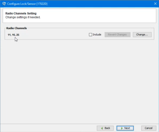
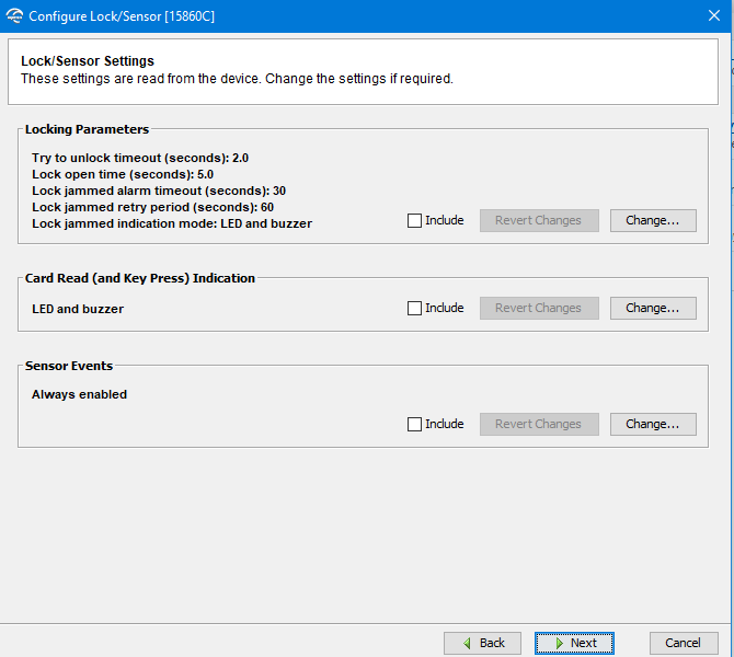
- Lock/Sensor Settings: Select Next to accept the default values:
- Device Settings: Select Next to accept the default values:
- Status Report Interval: 1 hour by default. (See Status Report Interval.)
- Battery Check Interval: 60 minutes by default.
- Polling Interval: 10 seconds by default.
- Device Update: Select Apply to transmit the configuration to the device. If you save a configuration, it can be applied to other devices. This function is available on the Lock/Sensor menu and Communication Hub menu and will only download settings that apply to the hardware selected. Select Save Configuration to open the Save Configuration dialog to save the configuration in local storage for later use.
- RFID Configuration: Select Next to accept the default values:
- To unpair the lock and hub, right-click on the lock, and then select Lock/sensor > Unpair lock/sensor from Communication Hub.
- Before the next step, follow the instructions in TLS Encryption Setup on the Configuration Web Page.
- When the configuration is complete, switch the devices from Manufacturer Mode to Customer Mode:
- Put the hub’s locks in Customer Mode. Right-click a lock in the list, and then select Lock/Sensor > Switch to Customer Mode. (Repeat for each lock as they must be in the same secure mode.)
- Make sure Enable TLS is selected on the ACU Settings screen. Select Change to open the ACU Settings, and then select Enable TLS. Select OK.
Put the IP hub in Customer Mode. Right-click on a record in the list, and then select Communication Hub > Switch to Customer Mode.
If the locks and hub are not in the same mode, this will result in a security mode conflict for the hub.
- If EAC is offline is reported, select Refresh from the ONLINE buttons.