Each Network Node enclosure has eight (8) slots in the aluminum chassis. The leftmost slot is reserved for the Network Node blade.
In addition, each enclosure supports up to seven (7) application extension blades in any combination. Three (3) types application extension blades are supported:
Access control blade (ACM): Includes two (2) Wiegand reader interfaces (Input Rated: 6V/70mA).
An access control blade is included in the Network Node enclosure.
An access control blade is compatible with UL listed Wiegand readers.
Input blade: Includes eight (8) supervised inputs (Input Rated: 6V/60mA).
Output blade: Includes eight (8) relay outputs (Input Rated: 6V/55mA).
To add application blades to your system in the future, see Install additional blades to install a slot-mounted blade in the Network Node enclosure.
This section describes how to connect readers, inputs, and outputs to the application extension blades in a Network Node enclosure.
Practical Guidelines for Effective Shielding
When wiring readers, inputs, outputs, and temperature sensors, follow the guidelines below for effective cable shielding:
Make sure your cable has sufficient shielding for the application’s needs. In moderately noisy environments, a foil alone may provide adequate protection. In noisier environments, consider braids or foil-braid combinations.
Use a cable suited to the application. Cables that experience repeated flexing should generally use a spirally wrapped shield rather than a braid. Avoid foil-only shielding on flex cables, because continuous flexing can tear the foil.
Make sure the equipment to which the cable is connected is properly grounded. Use an earth ground wherever possible and check the connection between the ground point and the equipment. Eliminating noise depends on a low impedance path to ground.
Most connector designs allow full 360° termination of the shield. Make sure the connector offers shielding effectiveness equal to that of the cable. For example, many common connectors are offered with metal-coated plastic, cast zinc, or aluminum backshells.
Ground the cable at one end. This eliminates the potential for noise-inducing ground loops.
Wire Readers
WARNING: Make sure all power is off before wiring and/or connecting any reader to a blade.
To wire readers:
Make sure you are grounded, and then pull the wiring through a knockout in the enclosure.
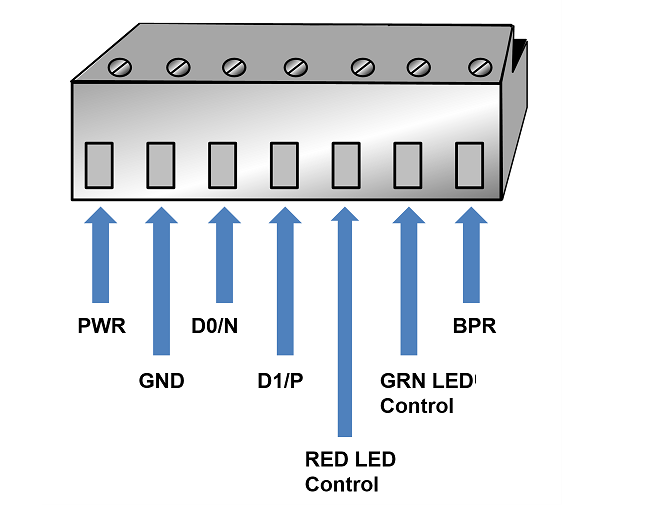
Wire specification: Refer to the reader manufacturer's installation guide for cable/wiring recommendations and maximum distance.Connect the reader wires to the 7-pin reader connector provided. Trim any excess wires so that there is no exposed conductor material. Wrap the excess wires around the outer jacket of the reader pigtail and secure it with electrical tape.
If this will be configured as a Wiegand reader, wire all seven pin connectors.
If this will be configured as an OSDP reader, wire only the first four pin connectors: Pwr, Gnd, D0/N, and D1/P.
D0/N corresponds to RS485 Negative, and D1/P corresponds to RS85 Positive. Refer to the reader manufacturer's documentation for installation instructions.
OSDP and encryption are supported only for readers on the current generation LenelS2 Access Control blade.
Plug the connector into a reader position on the access control blade.
Refer to the documentation provided by the reader manufacturer for wire colors.
Connect Readers to a Blade
WARNING: Make sure all power is off before connecting any reader to a blade.
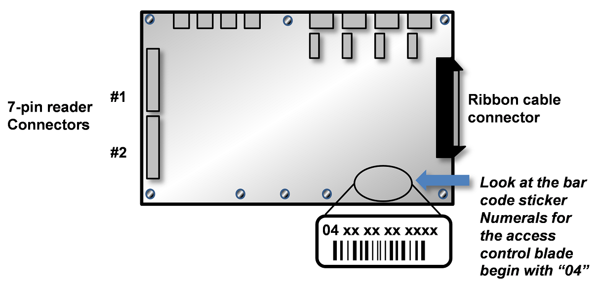
Access control blades have two 7-pin reader connectors mounted on the blade:
Each access control blade can supply a maximum of 400 milliamps peak power to the reader(s) (2.8A maximum is supplied). If the reader(s) connected to the access control blade draw more than 400 milliamps, external power must be supplied to these readers by a UL 294 or UL 603 Power Limited Supply.
The color-coded wires from the reader wiring harness must be connected to the 7-pin connector. The color-coding for Power (red), Ground (black), Data 0 (green), and Data 1 (white) is Security Industry Association (SIA) standard.
Reader Beeper control: This varies by manufacturer and model. Refer to the documentation provided by the reader manufacturer for details on your particular reader. Typically, the reader will beep for the duration of a momentary unlock, or until the door is opened. This occurs whether the door is unlocked by a valid card read or from the application. If no beeper is desired, do not connect the beeper control wire.
Reader LED control: This varies by manufacturer and model. Some use two-wire LED control and some use one-wire control. Refer to the documentation provided by the reader manufacturer for details on your particular reader. Control involving signal pulsing to change LED color is not supported.
The access control blade has both red and green LED control connections. The 7-pin reader connector location is shown in the 7-pin connector diagram.
LED display behavior for your particular reader may vary. Refer to the reader manufacturer documentation.
Wire Inputs
WARNING: Make sure all power is off before wiring and/or connecting any input to a blade.
Inputs are dry contact only. An input looks for a change in resistance, not a change in voltage.
To wire inputs:
Make sure you are grounded, and then pull the wiring through a knockout in the enclosure.
Wire specification: Refer to the input device manufacturer's installation guide for cable/wiring recommendations and maximum distance.Connect the input wires to the 2-pin input connector provided.
Make sure there is no power to the system, and then plug the connector into an input position on an access control blade or input blade. These connectors are polarized and can only be inserted one way.
If you are connecting previously wired or previously installed inputs, determine the input supervision type: normally open (NO) or normally closed (NC); zero, one, or two resistors; or single resistors in parallel or series.
You will need this information for the software setup of the input. See the section, Input supervision types.
Note: The system supports the of use of 1k Ohm resistor only.If you are installing the input device, refer to the input device manual to determine if the device circuit is normally open (NO) or normally closed (NC).
Select the input supervision type you want, and then install the supervision resistor(s) at the end of the input line.
Connect Inputs
WARNING: Make sure all power is off before connecting any input to a blade.
Inputs can be connected either to an access control blade or to an input blade.
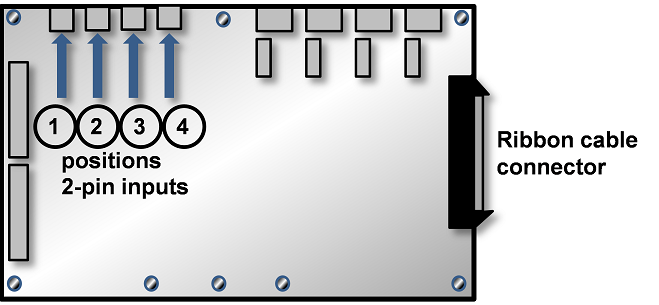
Access control blades have four male, 2-pin input connectors mounted on the blade:
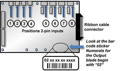
Input blades have eight male, 2-pin input connectors mounted on the blade:
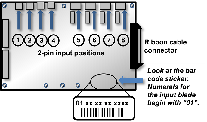
Input blades and temperature blades look very much alike. To tell them apart, look at the bar code sticker on the back of the blade. The numerals on the bar code sticker for an Input blade begin with "01", as shown above. The numerals on the bar code sticker for a Temperature blade begin with "08".
If more inputs are required beyond the four provided on the access control blade or the eight provided on the Input blade, additional access control or input blades can be installed in the enclosure. For instructions, see Install additional blades.
Input Supervision Types
Alarm input configuration is not evaluated by UL. Do not use for UL installations.
Use UL Listed EOL resistors.
The system supports the use of 1k Ohm resistors only.
Dual Resistor Input Circuits
The configuration of resistors shown here must be installed for supervised input resistance values to be properly read by the system:
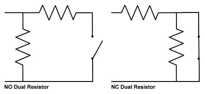
The configuration of resistors shown above must be installed for supervised input resistance values to be properly read by the system. The four states of the dual resistor input circuits are read according to these values:
Input State | Resistance Values |
|---|---|
Normal | 1k Ohms |
Alarm | 0.5k Ohms or 2k Ohms |
Short | 0k Ohms |
Open | No current (∞ Ohms) |
Normally Closed Parallel Resistor Input Circuits
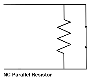
The three states of the normally closed parallel resistor input circuit are read according to these values:
Input State | Resistance Values |
|---|---|
Normal | 0k Ohms |
Alarm | 1k Ohms |
Open | No current (∞ Ohms) |
Normally Closed Series Resistor Input Circuits
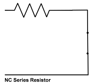
The three states of the normally closed series resistor input circuit are read according to the values:
Input State | Resistance Values |
|---|---|
Normal | 1k Ohms |
Alarm | No current (∞ Ohms) |
Short | 0k Ohms |
Normally Closed Unsupervised Input Circuits

The two states of the normally closed unsupervised input circuit are read according to the values:
Input State | Resistance Values |
|---|---|
Normal | 0k Ohms |
Alarm | No current (∞ Ohms) |
Normally Open Parallel Resistor Input Circuits
The three states of the normally open parallel resistor input circuit are read according to the values:
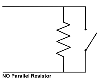
Input State | Resistance Values |
|---|---|
Normal | 1k Ohms |
Alarm | 0k Ohms |
Open | No current (∞ Ohms) |
Normally Open Series Resistor Input Circuits
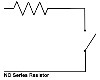
The three states of the normally open series resistor input circuit are read according to the values:
Input State | Resistance Values |
|---|---|
Normal | No current (∞ Ohms) |
Alarm | 1k Ohms |
Short | 0k Ohms |
Normally Open Unsupervised Input Circuits

The two states of the normally open unsupervised input circuit are read according to the values:
Input State | Resistance Values |
|---|---|
Normal | No current (∞ Ohms) |
Alarm | 0k Ohms |
Wire Outputs
WARNING: Make sure all power is off before wiring and/or connecting any output to a blade.
To wire outputs:
Make sure you are grounded, and then pull the wiring through a knockout in the enclosure.
Wire specification: Refer to the output device manufacturer's installation guide for cable/wiring recommendations and maximum distance.Refer to the output device manual to determine if the device is normally energized or normally not energized, and if it is DC or AC powered.
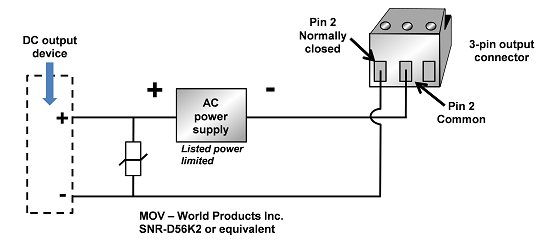
Connect the output wiring to the 3-pin output connector Pin 1 is normally closed (NC). Pin 2 is common. Pin 3 is normally open (NO).
Make sure there is no power to the LenelS2 Node, and then plug the connector into an output position on an access control blade or an output blade. These connectors are polarized and can only be inserted one way.
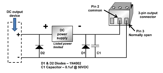
If the output device is DC powered and normally not energized, use the circuit shown in the following diagram:
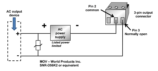
If the output device is AC powered and normally not energized, use the circuit shown in the following diagram:
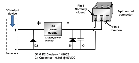
If the output device is DC powered and normally energized, use the circuit shown in the following diagram:
If the output device is AC powered and normally energized, use the circuit shown in the following diagram:
Connect Outputs
WARNING: Make sure all power is off before connecting any output to a blade. Perform all wire cutting terminations away from the enclosure because stray wire ends may come in contact with one of the blades and cause a short-circuit.
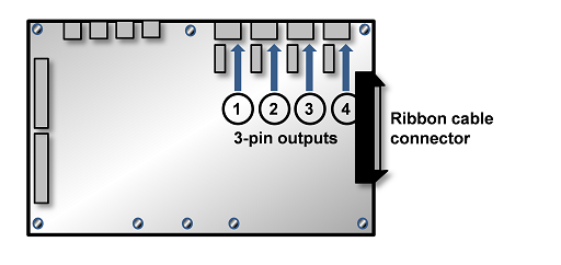
Outputs can be connected either to an access control blade or to an output blade. Access control blades have four 3-pin output connectors mounted on the blade, as shown:
Dry contacts are rated at 24 VDC/AC, 2A for resistive and inductive loads.
Output positions on the access control blade are output numbers 1, 2, 3, and 4.
If more outputs are required beyond the four provided on the access control blade, additional access control blades or output blades can be installed in the S2 node enclosure. For instructions, see Install additional blades.
Output blades have eight male, 3-pin output connectors mounted on the blade, as shown below. Outputs support any output device that operates on the following maximum electrical ratings: 24 VDC/AC, 2A for resistive and inductive loads.
WARNING: The diodes and varistors shown in the diagrams above must be installed as indicated. They are designed to protect the output circuits from induced voltage spikes, which can damage the output circuitry on the blade.
© 2026 Honeywell International Inc. All Rights Reserved.