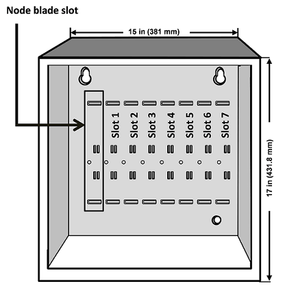
The Network Node enclosure has eight (8) slots in the aluminum chassis. The leftmost slot is reserved for the Network Node blade running the node software (Input Rated: 12V/178mA). The provided access control blade is mounted to its right, in Slot 1. The remaining slots, numbered 2 through 7, can hold any combination of access control, input, and output application extension blades.
How to Determine Slot and Position Numbers
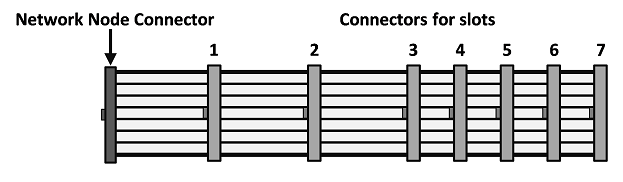
Regardless of the physical slot in which a blade is mounted, its slot number is determined by the ribbon-cable connector you plug into the blade. This is because the ribbon cable (shown in the diagram above) is a bus, and a blade’s position on the bus determines its slot number.
For example, even if a blade is mounted in physical Slot 3, if it is attached to ribbon cable connector 4, the application will see it in Slot 4 on the bus.
IMPORTANT: The blade running the node Network Node software must be attached to the leftmost connector on the ribbon cable.
Position numbers are determined by the connector position on the blade itself. For more information, see Connect readers, inputs, and outputs.
WARNING: Blades are not hot-swappable. Before connecting or disconnecting blades in the enclosure, be sure to remove power from the system after stopping all processes.
To install a slot-mounted blade in the Network Node enclosure:
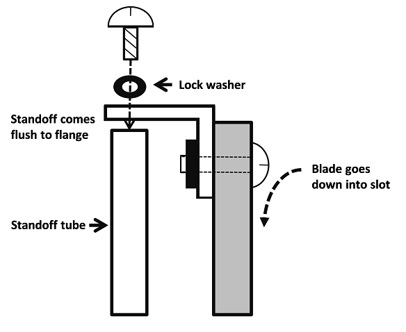
Thread the provided standoff tube down onto the threaded post on the chassis, next to the slot where you will insert the additional blade.
Be sure that you are grounded, and then insert the additional blade into the slot on the chassis with the ribbon cable connector toward the bottom of the enclosure.
Place the provided lock washer over the top of the standoff, and thread the provided screw through the flange and down into the top of the standoff and snugly down onto the lock washer as shown:
Connect the ribbon cable from the blade in the leftmost slot to the newly installed blade.
The connector is polarized. Make sure that the center bump fits into the opening for it on the connector located on the blade.Press the connector firmly into place until you hear the click of the extraction levers snapping into vertical position. You may have to press the extraction levers into the full vertical position before you will hear the click.