Wire the Network Connection
Networking is not evaluated by UL. Only standalone systems are evaluated.
To wire the network connections:
Pull the Ethernet cable through a knockout in the enclosure.
Cable specification: CAT-5 or greater with an RJ-45 connector wired straight through, connecting to a network hub, switch, or router.Connect the Ethernet cable to the RJ-45 network connector, labeled "Network Port" in Figure 1.
If the network connection is functioning properly, the Amber LED on the network switch will light.
Wire Power
This section describes how to connect the Network Node enclosure to a power source. All installations must be conducted by a qualified electrician in accordance with National Electrical code (NEC) or specific country local wiring rules.
WARNING: Do not apply power to the system until all connections have been made for readers, inputs, and outputs. Refer to Connect readers, inputs, and outputs for information on connecting these resources.
The AC power must be 100-240VAC, 50-60 Hz. Power must come from a separate circuit with its own breaker and an isolated earth ground. Disconnect device (breaker) will connect both poles simultaneously.
A minimum of 14 AWG (2.5 mm2) wires must be used for installation. Wiring must be protected at the building source by a 15A circuit breaker (or 16A for EU installations). This circuit breaker is the main disconnect device and must be readily accessible.
A minimum 14 AWG (2.5 mm2) earthing conductor must also be provided and connected to the earth stud as indicated in the wiring diagram.
To wire AC power:
Make sure the AC power is turned off.
Use the knock-out that is physically closest to the terminal block if you are using single-insulated wire. If one of the other knock-outs is used, you must use double-insulated wire. The conduit or equivalent must be installed in the knock-out to prevent accidental contact with the AC power connections.
Make sure all conduit and enclosure openings are free of sharp edges.
Connect the green/yellow ground, or earth, wire to the ground stud marked with the following symbol on the bottom of the enclosure:

Remove the plastic cover from the terminal block.
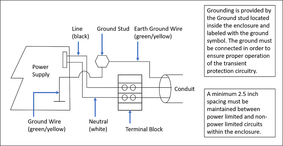
Connect the AC power to the two-position terminal block.
The positive wire from the AC power source must be connected to the same side of the junction block as the black wire from the unit’s power supply.
The Neutral wire must be connected to the same side of the junction block as the white wire from the unit’s power supply.
The connection between the power supply and the junction box is prewired.Replace the plastic cover on the junction block to ensure that no hot leads are exposed.
Provide AC wiring to the wall mount enclosure.
The Network Node Blade
Figure 1 shows the node blade components that run the Network Node application software:
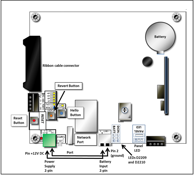
WARNING: There is risk of explosion if the onboard coin battery is replaced with the incorrect type. Replace only with the same or equivalent type recommended by the manufacturer. Dispose of used batteries according to the manufacturer’s instructions and local requirements.
Node blade's onboard coin battery specification: Panasonic CR2450, 3V.
Network Node Blade LED Indications
LEDs located on the Network Node blade are described in the following table.
LED | State | Color | Description |
|---|---|---|---|
CPU (D911) | ON | YELLOW | Blinking indicates node CPU activity. |
OFF | No CPU activity. | ||
DC IN (D2209) | GREEN | DC IN powers the board. | |
BATT (D2210) | GREEN | SLA battery powers the board. | |
LD1 - LD4 (D930 to D933) | ON | Used by Technical Support for testing and debugging. | |
OFF | |||
Network Port | ON | AMBER | Network data transfer rate is 100 mbs |
OFF | Network data transfer rate is 10 mbs | ||
ON | GREEN | Network data transfer rate is 100 mbs | |
OFF | Network data transfer rate is 10 mbs | ||
Reverse Polarity (D0203) | ON | RED | Polarity has been wired in reverse. |
OFF | Polarity has been wired correctly. | ||
Run (D910) | ON | BLUE | System is running. |
OFF | System is offline. |
Buttons on the Network Node Blade
Button | Function |
|---|---|
The Hello button is located near the Tamper Switch connector. 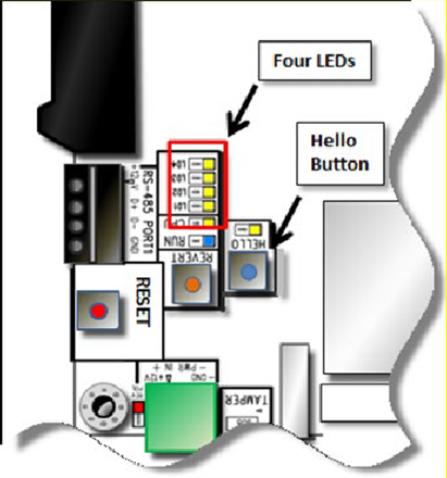 | Pressing the Hello button sends a "Hello" indication to the Network Node's embedded web server. This identification stays active for two minutes. If a USB flash drive is plugged in to the Network Node’s USB connector, (after waiting about 5 seconds for it to be recognized) the system will write its network configuration to or from the flash drive. 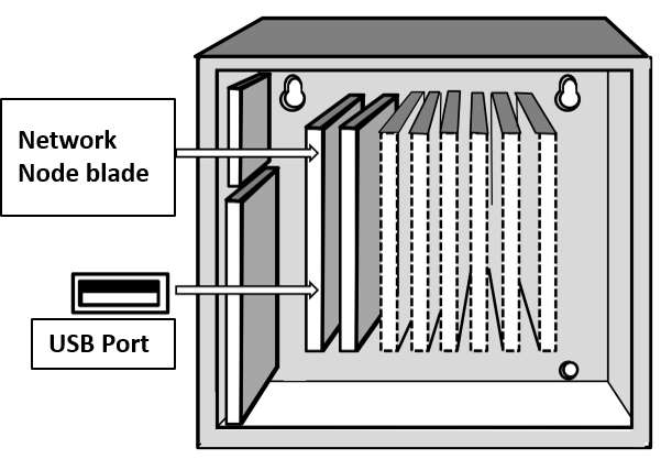 |
The Reset button is located near the Revert button and the green Power connector. 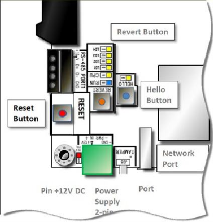 | Pressing the Reset button resets the Network Node’s CPU, causing it to reboot. It will take approximately 25 seconds for the node to reboot and reconnect to the Elements gateway When the node reconnects to the gateway, the current system configuration is loaded onto the node. |
The Revert button is located near the green Power connector and the column of LEDs. 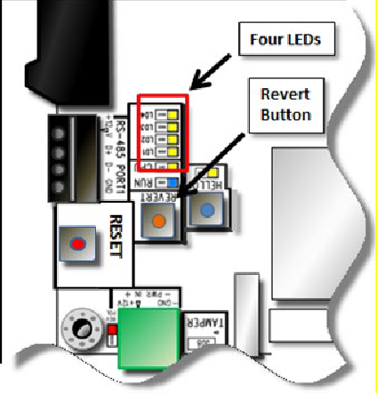 | When you hold down the Revert button for at least 10 seconds, the four LEDs next to the button start to light up and then begin blinking on and off. Once all four buttons are blinking on and off at the same time, release the button and the revert will occur, returning the Network Node to its factory default settings:
|