The LNL-1320 Board
The LNL-1320 reader interface boards provide a solution to the host system integrator for interfacing to a TTL (D1/D0, Clock/Data) or 2-wire RS-485 device and door hardware. The LNL-1320 provides a tri-state LED control and buzzer control. Six (6) Form-C relay outputs may be used for strike control or alarm signaling. Eight (8) inputs are provided that may be used for monitoring the door contact, request to exit push button and alarm contacts. Input circuits can be configured as unsupervised or supervised.
The LNL-1320 communicates to the controller via a 2-wire RS-485.
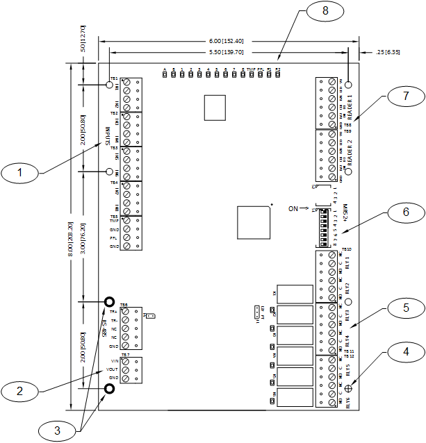
See the following diagram for component location (some components shown are not present on the LNL-1320).
The LNL-1320 Board Callouts
Callout | Description |
|---|---|
1 | Inputs |
2 | DC input power |
3 | Earth ground (connection not required) |
4 | Eight (8) mounting holes (Ø0.156 [Ø4.0]) |
5 | Output relays |
6 | DIP switches |
7 | Reader interface |
8 | Status LEDs |
Supplying Power to the LNL-1320
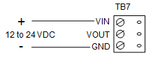
The LNL-1320 accepts 12 to 24 VDC for power on TB7 (VIN and GND). Locate the power source as close to the LNL-1320 as possible. Make power connection with minimum of 18 AWG wires.
Observe POLARITY on VIN!
The VOUT terminal on TB7 is the same as VIN.
Communication Wiring (SIO Communication Port)
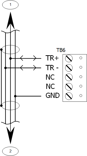
The LNL-1320 communicates to a Lenel intelligent controller (LNL-3300, for example) via a 2-wire RS-485 interface. The LNL-1320 allows for multi-drop communication on a bus of up to 4000 feet (1219 m). Use twisted pair (minimum 24 AWG) with drain wire and shield for communication. See Specifications section.
Install RS-485 termination jumper, J4, on the interface boards at each end of the communication line only.
Communication Wiring (SIO Communication Port) Callouts
Callout | Description |
|---|---|
1 | To all other devices on the bus |
2 | To all other devices on the bus |
ONLY 2-WIRE RS-485 IS SUPPORTED | |
Reader Wiring
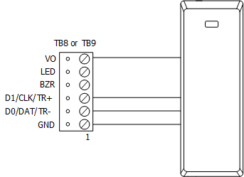
Each reader port supports a reader with TTL (D1/D0, Clock/Data), or 2-wire RS-485 signaling. Power to the reader is selectable: 12 VDC (VIN must be greater than 20 VDC), or power is passed-through (PT) from the input voltage of the LNL-1320 (TB7-VIN), 300 mA maximum per reader port. Readers that require different voltage or have high current requirements must be powered separately. (Refer to the reader manufacturer specifications for cabling requirements.) In the 2-wire LED mode, the buzzer output is used to drive the second LED. Reader port configuration is set via the host software.
To fully utilize each reader port:
- TTL signaling requires a 6-conductor cable (18 AWG).
- RS-485 signaling requires two 2-conductor cables. Use one (1) cable for power (18 AWG) and one (1) cable for communication (24 AWG, with drain wire and shield).
12V PT | J1 - Reader Port Power Select |
|---|---|
| 12 VDC is available on reader ports (VIN is greater than or equal to 20 VDC). |
| VIN power is “passed through” to reader ports. |
Note
Install jumper J1 in the 12V position ONLY if the input voltage (VIN) is greater than 20 VDC. Failure to do so may damage the reader to the LNL-1320.
Typical D1/D0 - Clock/Data Reader
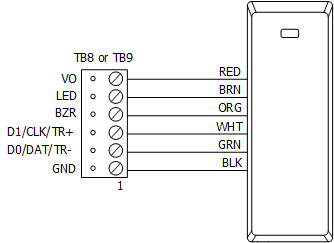
Typical 2-Wire RS-485 Device (such as OSDP Reader)
Alarm Contact Wiring
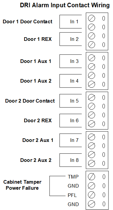
There are eight (8) inputs that are typically used to monitor door position, request to exit, or alarm contacts. Input circuits can be configured as:
Unsupervised alarm (2 states); reporting as an open or closed contact.
Supervised alarm (6 states); reporting as an open or closed contact, open circuit, shorted circuit, grounded circuit , or foreign voltage.
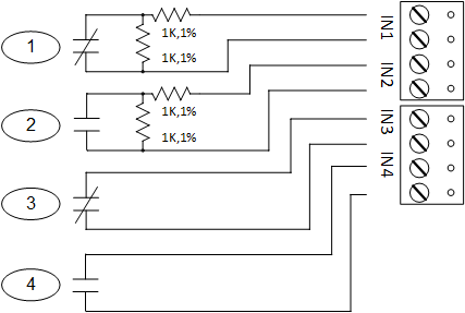
These inputs are connected using the IN1, IN2, IN3, IN4, IN5, IN6, IN7, and IN8 inputs. The standard wiring configuration is as follows:
A supervised input circuit requires adding two (2) resistors with a value of 1k ohm, 1% to the circuit to facilitate proper reporting and should be located as close to the sensor as possible. Custom end of line (EOL) resistances may be configured via the host software.
The input circuit wiring configurations shown are supported but may not be typical.
Alarm Contact Wiring Callouts
Callout | Description |
|---|---|
1 | Standard supervised circuit |
2 | Standard supervised circuit |
3 | Unsupervised circuit |
4 | Unsupervised circuit |
Inputs for Cabinet Tamper/Power Fault
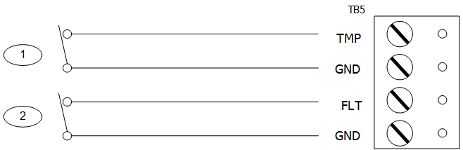
Input CT and input BA are used for monitoring cabinet tamper and power failure with normally closed contact. These two inputs are for contact closure monitoring only and do not use EOL resistor(s). If these inputs are not used, install a short piece of wire at the input to indicate a safe condition.
Inputs for Cabinet Tamper/Power Fault Callouts
Callout | Description |
|---|---|
1 | Cabinet tamper |
2 | Power fault |
Output Relay Wiring
Six (6) Form-C contact relays are provided for controlling door strikes or other devices. Load switching can cause abnormal contact wear and premature contact failure. Switching of inductive loads (strike) also causes EMI (electromagnetic interference) which may interfere with normal operation of other equipment. To minimize premature contact failure and to increase system reliability, a contact protection circuit must be used. The following two (2) circuits are recommended. Locate the protection circuit as close to the load as possible (within 12 inches [30 cm]), as the effectiveness of the circuit will decrease if it is located farther away.
Use sufficiently large gauge of wires for the load current to avoid voltage loss.
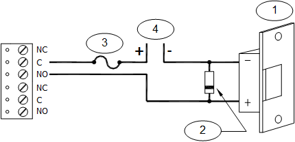
Output Relay Wiring Callouts
Callout | Description |
|---|---|
1 | DC strike |
2 | Diode |
3 | Fuse |
4 | To DC power source |
Diode Selection: Diode current rating: 1x strike current. Diode breakdown voltage: 4x strike voltage. For 12 VDC or 24 VDC strike, diode 1N4002 (100V/1A) typical.
Jumper and DIP Switch Usage
Jumper | Description |
|---|---|
J1 | Reader Power Select |
12V = 12 VDC at reader ports. *** See note below *** | |
PT = VIN "passed through" to reader ports | |
J4 | RS-485 Termination, install in first and last units, only |
All other jumpers are for factory use only | |
Note
Install jumper J1 in the 12V position ONLY if the input voltage (VIN) is greater than 20 VDC. Failure to do so may damage the reader to the LNL-1320.
DIP Switches
Switches 1 to 5 select the device address. Switches 6 and 7 select the communication baud rate. Switch 8 enables encrypted communication. All other configuration settings are set via the host software.
DIP switch(es) | Used to configure |
|---|---|
1, 2, 3, 4, 5 | Device communication address (0-31) |
6, 7 | Communication baud rate |
8 | Downstream encryption (available with OnGuard® 2009 or later) |
Device Address
Address | DIP switch | ||||
|---|---|---|---|---|---|
5: | 4: | 3: | 2: | 1: | |
0 | off | off | off | off | off |
1 | off | off | off | off | ON |
2 | off | off | off | ON | off |
3 | off | off | off | ON | ON |
4 | off | off | ON | off | off |
5 | off | off | ON | off | ON |
6 | off | off | ON | ON | off |
7 | off | off | ON | ON | ON |
8 | off | ON | off | off | off |
9 | off | ON | off | off | ON |
10 | off | ON | off | ON | off |
11 | off | ON | off | ON | ON |
12 | off | ON | ON | off | off |
13 | off | ON | ON | off | ON |
14 | off | ON | ON | ON | off |
15 | off | ON | ON | ON | ON |
16 | ON | off | off | off | off |
17 | ON | off | off | off | ON |
18 | ON | off | off | ON | off |
19 | ON | off | off | ON | ON |
20 | ON | off | ON | off | off |
21 | ON | off | ON | off | ON |
22 | ON | off | ON | ON | off |
23 | ON | off | ON | ON | ON |
24 | ON | ON | off | off | off |
25 | ON | ON | off | off | ON |
26 | ON | ON | off | ON | off |
27 | ON | ON | off | ON | ON |
28 | ON | ON | ON | off | off |
29 | ON | ON | ON | off | ON |
30 | ON | ON | ON | ON | off |
31 | ON | ON | ON | ON | ON |
Communication Baud Rate
Baud rate | DIP switch 6: | DIP switch 7: |
|---|---|---|
38,400 bps | ON | ON |
19,200 bps | off | ON |
9600 bps | ON | off |
115,200 bps | off | off |
Bus Encryption
Bus communications | DIP switch 8: | DIP switch 8: |
|---|---|---|
Encryption is not required | off | Normal operation |
Encryption is required | ON | Not allowed |
Status LEDs
Power-up: All LEDs OFF
Initialization: Once power is applied, initialization of the module begins.
When initialization is completed, LEDs A through R2 are briefly sequenced ON then OFF.
Run time: After the above sequence, the LEDs have the following meanings:
A LED: Heartbeat and On-Line Status:
- Off-line: 1 sec rate, 20% ON
- On-line:
- Non-encrypted communication: 1 second rate, 80% ON
- Encrypted communication: 0.1 sec ON, 0.1 sec OFF, 0.1 sec ON, 0.1 sec OFF, 0.1 sec ON, 0.1 sec OFF, 0.1 sec ON, 0.3 sec OFF
A LED: Error Indication:
Waiting for application firmware to be downloaded: 0.1 sec ON, 0.1 sec OFF.
B LED: Serial I/O Communication Port Status:
Indicates communication activity on the serial I/O communication port:
1 LED: Input Status: IN1
2 LED: Input Status: IN2
3 LED: Input Status: IN3
4 LED: Input Status: IN4
5 LED: Input Status: IN5
6 LED: Input Status: IN6
7 LED: Input Status: IN7
8 LED: Input Status: IN8
TMP: Cabinet Tamper
PFL: Power Fault
Input in the inactive state: OFF (briefly flashes ON every 3 seconds)
Input in the active state: ON (briefly flashes OFF every 3 seconds)
Input in a trouble state: Rapid Flash
R1 LED: reader port 1:
- Clock/Data Mode: Flashes when data is received, either input
- D1/D0 Mode: Flashes when data is received, either input
- RS-485 Mode: Flashes when transmitting data
R2 LED: reader port 2:
- Clock/Data Mode: Flashes when data is received, either input
- D1/D0 Mode: Flashes when data is received, either input
- RS-485 Mode: Flashes when transmitting data
K1 through K6 LEDs: Illuminates when output relay RLY 1 (K1) through RLY 6 (K6) is energized.
Every three (3) seconds, LEDs A through R2 are pulsed to their opposite state for 0.1 sec.
Specifications
The LNL-1320 is for use in low voltage, class 2 circuits only. These specifications are subject to change without notice. The installation of this device must comply with all local fire and electrical codes.
- Primary power: 12 to 24 VDC ± 10%, 550 mA maximum (reader current not included)
- Outputs: Six (6) Form-C relays:
- Normally open (NO) contact: 5 A @ 30 VDC resistive
- Normally closed (NC) contact: 3 A @ 30 VDC resistive
- Inputs:
- Eight (8) unsupervised/supervised, standard EOL: 1k/1k ohm, 1%, ¼ watt
- Two (2) unsupervised, dedicated for cabinet tamper and UPS fault monitoring
- Reader interface:
- Power (jumper selectable): 12 VDC ± 10% regulated, 300 mA maximum each reader (input voltage (VIN) must be > 20 VDC) or 12 to 24 VDC ± 10% (input voltage passed through), 300 mA maximum each reader
- Data Inputs: TTL compatible or 2-wire RS-485
- LED Output: TTL compatible, high > 3 V, low < 0.5 V, 5 mA source/sink maximum
- Buzzer Output: Open collector, 12 VDC open circuit maximum, 40 mA sink maximum
- Communication: 2-wire RS-485: 9600, 19200, 38400, or 115200 bps
- Cable requirements:
- Power: 1 twisted pair, 18 AWG
- RS-485 I/O devices: 1 twisted pair with drain wire and shield, 24 AWG, 120 ohm impedance, 4000 feet (1219 m) maximum
- Alarm inputs: 1 twisted pair per input, 30 ohms maximum
- Outputs: As required for the load
- Reader data (TTL): 6-conductor, 18 AWG, 500 feet (150 m) max
- Reader data (RS-485): 1 twisted pair with drain wire and shield, 24 AWG, 120 ohm impedance, 2000 feet (610 m) maximum
- Mechanical:
- Dimension: 6 x 8 x 1 in. (152 x 203 x 25 mm)
- Weight: 11 oz. (312 g) nominal
- Environmental:
- Temperature: -55 to +85 °C storage, 0 to +70 °C operating
- Humidity: 5 to 95% RHNC
These specifications are subject to change without notice.
Regulatory Information
FCC Compliance
This device complies with part 15 of the FCC Rules. Operation is subject to the following two conditions: (1) This device may not cause harmful interference, and (2) this device must accept any interference received, including interference that may cause undesired operation.
Liability
It is expressly understood and agreed that the interface should only be used to control exits from areas where an alternative method for exit is available. This product is not intended for, nor is rated for operation in life-critical control applications. LenelS2 is not liable under any circumstances for loss or damage caused by or partially caused by the misapplication or malfunction of the product. LenelS2’s liability does not extend beyond the purchase price of the product.
Certifications
For certification information, refer to the hardware documentation for the host application.
Product Warnings and Disclaimers
THESE PRODUCTS ARE INTENDED FOR SALE TO, AND INSTALLATION BY, AN EXPERIENCED SECURITY PROFESSIONAL. LENELS2 CANNOT PROVIDE ANY ASSURANCE THAT ANY PERSON OR ENTITY BUYING ITS PRODUCTS, INCLUDING ANY “AUTHORIZED DEALER”, IS PROPERLY TRAINED OR EXPERIENCED TO CORRECTLY INSTALL SECURITY RELATED PRODUCTS. FOR MORE INFORMATION ON PRODUCT WARNINGS AND DISCLAIMERS, SEE THE "LENELS2 PRODUCT WARNINGS AND DISCLAIMERS" KNOWLEDGE BASE ARTICLE IN THE LENELS2 KNOWLEDGE BASE. THIS INFORMATION IS SUBJECT TO CHANGE WITHOUT NOTICE.