General
The LNL-1300 reader interface provides a solution to the host system integrator for interfacing to a TTL (D1/D0, Clock/Data) or RS-485 device, and door hardware. It also provides a tri-stated LED control and buzzer control. Two (2) Form-C contact relay outputs may be used for strike control or alarm signaling. Two (2) inputs are provided that can be used for monitoring the door contact and request to exit push button. Input circuits can be configured as unsupervised or supervised. Communication to the controller is accomplished via a 2-wire RS-485 interface. The LNL-1300 requires 12 to 24 VDC for power.
LNL-1300 Series 3 Hardware
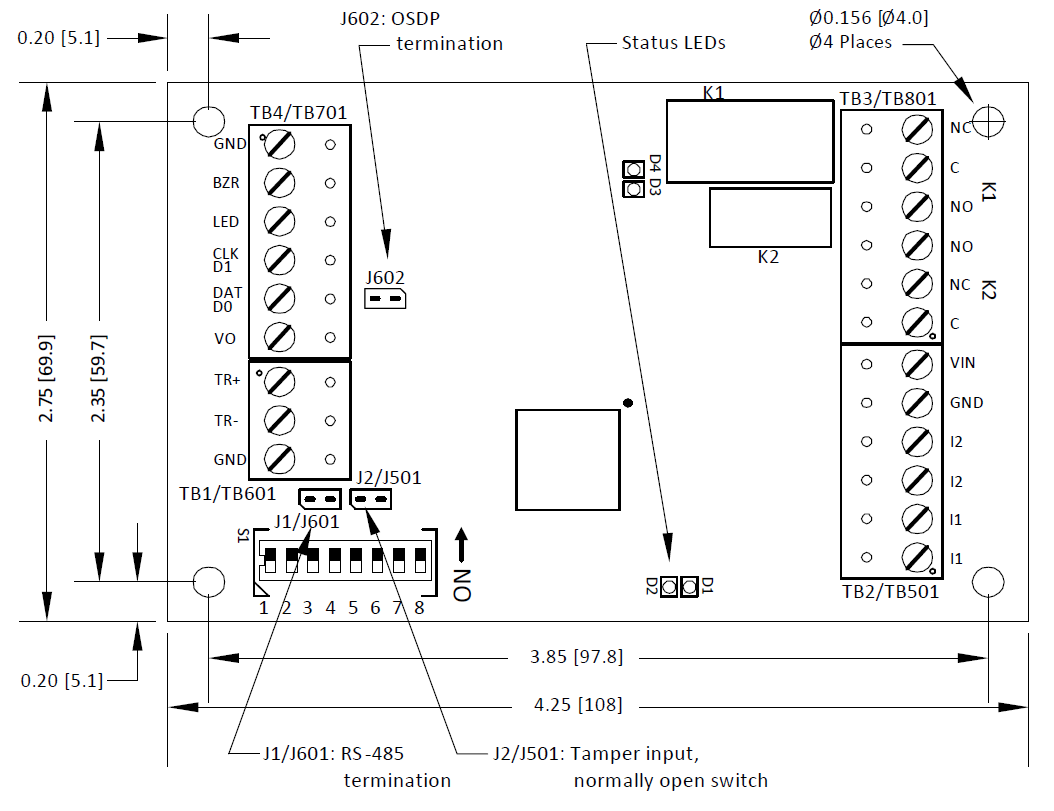
Notes: Older versions of the LNL-1300 Series 3 do not include the OSDP termination jumper J602.
Diagrams include jumper and terminal block labels for all versions such as: J1/J601, TB2/TB501.
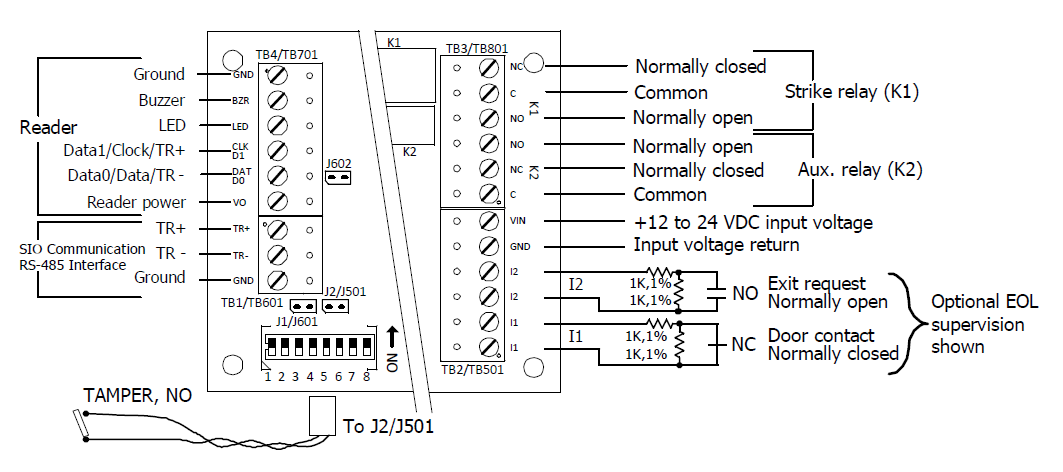
Supplying Power to the LNL-1300 Series 3
The LNL-1300 requires filtered 12 to 24 VDC ± 10% for power. Two (2) inputs are typically used for door contact and exit push button monitoring. End of line resistors are required input supervision, shown below.
Note: The input power is passed through to the reader terminal strip and is available for powering a reader. Readers that require different voltage requirements must be powered separately. Care must be taken to insure the input voltage is within the voltage range of the reader. The reader power output terminal, TB4-6/TB701-6 (VO), is not current-limited.
J602 OSDP Termination Jumper
The J602 jumper is located next to the reader port and controls OSDP termination. This jumper should be closed when an OSDP reader is used. When using a non-OSDP reader, the jumper should be open.
Important: Failure to properly set the OSDP termination jumper could cause reader communication issues.
Note: Older versions of the LNL-1300 Series 3 do not include the OSDP termination jumper J602.
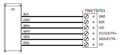
Reader Wiring
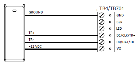
The reader port supports a reader with TTL (D1/D0, Clock/Data) or 2-wire RS-485 signaling. (Refer to the reader manufacture specifications for cabling requirements.) In the 2-wire LED mode the buzzer output is used to drive the second LED. Reader port configuration is set via the host software.
Notes: For OSDP cable lengths greater than 200 ft (61 m) or EMF interference close jumper J602.
For older versions of the LNL-1300-S3 that do not include jumper J602, install a 120Ω +/- 2Ω resistor across RS-485 termination ends.
Data 0 and Data 1 wires for Wiegand may be reused for OSDP. However, standard Wiegand cable may not meet RS-485 twisted pair recommendations. The reuse of cable works best on shorter cable lengths at lower data rates.
Typical D1/D0 or Clock/Data Reader
Typical RS-485 Device (such as OSDP Reader)
Door Strike Relay Wiring
Two (2) Form-C contact relays are provided for controlling door strike or other devices. See Specifications section for the relay contact ratings. Load switching can cause abnormal contact wear and premature contact failure. Switching of inductive loads (strike) also causes EMI (electromagnetic interference) which may interfere with normal operation of other equipment. To minimize premature contact failure and to increase system reliability, a contact protection circuit must be used. The following circuit is recommended. Locate the protection circuit as close to the load as possible (within 12 inches [30 cm]), as the effectiveness of the circuit will decrease if it is located far away.
Typical DC Door Strike Wiring
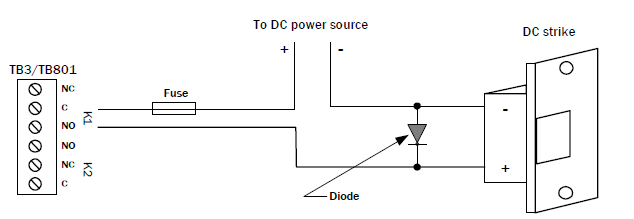
Diode Selection:
- Diode current rating: greater than 1x strike current.
- Diode breakdown voltage: 4x strike voltage.
- For 12 VDC or 24 VDC strike, diode 1N4002 (100V/1A) typical.
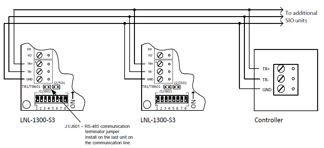
Communication Wiring
The LNL-1300 communicates with a LenelS2 intelligent controller (LNL-3300, for example) via a half-duplex, multi-drop 2-wire RS-485 interface. The total cable length is limited to 4000 feet (1219 m). A shielded cable of 24 AWG with characteristic impedance of 120 ohm is specified for the 2-wire RS-485 interface. The last device on each end of the communication line should have the terminator installed (install jumper J1/J601).
Address, Baud Rate, and Encryption Configuration Switch
Switches 1 to 5 select the device address. Switches 6 and 7 select the communication baud rate. Switch 8 enables encrypted communication. All other configuration settings are set via the host software.
Device Address
Address | DIP switch | ||||
|---|---|---|---|---|---|
5: | 4: | 3: | 2: | 1: | |
0 | off | off | off | off | off |
1 | off | off | off | off | ON |
2 | off | off | off | ON | off |
3 | off | off | off | ON | ON |
4 | off | off | ON | off | off |
5 | off | off | ON | off | ON |
6 | off | off | ON | ON | off |
7 | off | off | ON | ON | ON |
8 | off | ON | off | off | off |
9 | off | ON | off | off | ON |
10 | off | ON | off | ON | off |
11 | off | ON | off | ON | ON |
12 | off | ON | ON | off | off |
13 | off | ON | ON | off | ON |
14 | off | ON | ON | ON | off |
15 | off | ON | ON | ON | ON |
16 | ON | off | off | off | off |
17 | ON | off | off | off | ON |
18 | ON | off | off | ON | off |
19 | ON | off | off | ON | ON |
20 | ON | off | ON | off | off |
21 | ON | off | ON | off | ON |
22 | ON | off | ON | ON | off |
23 | ON | off | ON | ON | ON |
24 | ON | ON | off | off | off |
25 | ON | ON | off | off | ON |
26 | ON | ON | off | ON | off |
27 | ON | ON | off | ON | ON |
28 | ON | ON | ON | off | off |
29 | ON | ON | ON | off | ON |
30 | ON | ON | ON | ON | off |
31 | ON | ON | ON | ON | ON |
Communication
Baud rate | DIP switch 6: | DIP switch 7: |
|---|---|---|
38,400 bps | ON | ON |
19,200 bps | off | ON |
9600 bps | ON | off |
115,200 bps (Firmware revisions prior to 1.38.1, this setting is 2,400 BPS.) | off | off |
Bus communications | DIP switch 8: | DIP switch 8: |
|---|---|---|
Encryption is not required | off | Normal operation |
Encryption is required | ON | Not allowed |
Status LEDs
Power-up: All LEDs OFF.
Initialization: Once power is applied, initialization of the module begins. The D1 LED is turned ON at the beginning of initialization.
Run time: After the above sequence, the LEDs have the following meanings:
LED | Description |
|---|---|
D1 LED heartbeat and on-line status | Off-line: 1 sec rate, 20% ON, 80% OFF |
On-line: Non-encrypted communication: 1 sec rate, 80% ON, 20% OFF Encrypted communication: .1 sec ON, .1 sec OFF, .1 sec ON, .1 sec OFF, .1 sec ON, .1 sec OFF, .1 sec ON, .3 sec OFF | |
D1 LED | Error Indication: Waiting for application firmware to be downloaded: .1 sec ON, .1 sec OFF. |
D2 LED | SIO Communication Port Status: Indicates communication activity on the SIO communication port. |
Specifications
The LNL-1300 Series 3 is for use in low voltage, Class 2 circuits only.
The installation of this device must comply with all local fire and electrical codes.
- Primary power: 12 to 24 VDC ± 10%, 150 mA maximum (reader current not included)
- Outputs: Two (2) Form-C relays:
K1: Normally open (NO) contact: 5 A @ 30 VDC resistive
Normally closed (NC) contact: 3 A @ 30 VDC resistiveK2: 1 A @ 30 VDC resistive
- Inputs:
Two (2) unsupervised/supervised, standard EOL: 1k/1k ohm, 1%, ¼ watt
One (1) unsupervised, dedicated for cabinet tamper
- Reader interface:
- Power: 12 to 24 VDC ± 10% (input voltage (VIN) passed through)
Data Inputs: TTL compatible or 2-wire RS-485
LED Output: TTL compatible, high > 3 V, low < 0.5 V, 5 mA source/sink maximum
Buzzer Output: Open collector, 12 VDC open circuit maximum, 40 mA sink maximum
- Communication: 2-wire RS-485: 9600, 19200, 38400, or 115200 bps
- Cable requirements:
Power: 1 twisted pair, 18 AWG
RS-485 I/O Devices: 1 twisted pair with drain wire and shield, 24 AWG, 120 ohm impedance, 4000 feet (1219 m) maximum
Alarm Input: 1 twisted pair per input, 30 ohm maximum
Outputs: As required for the load
Reader data (TTL): 6-conductor, 18 AWG, 500 feet (150 m) maximum
Reader data (RS-485): 1 twisted pair with drain wire and
- Mechanical:
- Dimension: 4.25in. (108 mm) W x 2.75 in. (70 mm) L x 1 in. (25.4 mm) H
- Weight: 4 oz. (120 g) nominal
- Environmental:
Temperature: Storage: -55 to +85 °C (-67° to 185° F)
Operating: -40 to +70 °C (40° to 158° F)Humidity: 5 to 95% RHNC
These specifications are subject to change without notice.
Regulatory Information
FCC Compliance
This device complies with part 15 of the FCC Rules. Operation is subject to the following two conditions: (1) This device may not cause harmful interference, and (2) this device must accept any interference received, including interference that may cause undesired operation.
Liability
It is expressly understood and agreed that the interface should only be used to control exits from areas where an alternative method for exit is available. This product is not intended for, nor is rated for operation in life-critical control applications. LenelS2 is not liable under any circumstances for loss or damage caused by or partially caused by the misapplication or malfunction of the product. LenelS2’s liability does not extend beyond the purchase price of the product.
Certifications
For certification information, refer to the hardware documentation for the host application.
Product Warnings and Disclaimers
THESE PRODUCTS ARE INTENDED FOR SALE TO, AND INSTALLATION BY, AN EXPERIENCED SECURITY PROFESSIONAL. LENELS2 CANNOT PROVIDE ANY ASSURANCE THAT ANY PERSON OR ENTITY BUYING ITS PRODUCTS, INCLUDING ANY “AUTHORIZED DEALER”, IS PROPERLY TRAINED OR EXPERIENCED TO CORRECTLY INSTALL SECURITY RELATED PRODUCTS. FOR MORE INFORMATION ON PRODUCT WARNINGS AND DISCLAIMERS, SEE THE "LENELS2 PRODUCT WARNINGS AND DISCLAIMERS" KNOWLEDGE BASE ARTICLE IN THE LENELS2 KNOWLEDGE BASE. THIS INFORMATION IS SUBJECT TO CHANGE WITHOUT NOTICE.