Intelligent Controller LNL-X2210 with Paired Reader Interface for One Physical Barrier
Download the LNL-X2210 Quick Reference PDF
For detailed information, refer to the hardware documentation for the host application.
General
The LNL-X2210 intelligent controller provides decision making, event reporting and database storage for the Lenel hardware platform. Two reader interfaces configured as paired or alternate readers provide control for one physical barrier.
Host communication is via the on-board 10-BaseT/100Base-TX Ethernet port.
Reader port 1 can accommodate a reader that utilizes TTL (D1/D0, Clock/Data) or 2-wire RS-485 device signaling (for example an OSDP reader), also provides tri-state LED control, and buzzer control (one wire LED mode only). This port can also utilize multiple 2-wire RS-485 multi-dropped devices, such as up to two OSDP readers or up to eight remote serial I/O devices.
Reader port 2 can accommodate a reader that utilizes TTL (D1/D0 or Clock/Data) signaling, also provides tri-state LED control, and buzzer control (one wire LED mode only). Two Form-C contact relay outputs may be used for door strike control or alarm signaling. The relay contacts are rated at 2 A @ 30 VDC, dry contact configuration. Two inputs are provided that may be used for monitoring the door contact, exit push button or alarm contact. Input circuits can be configured as unsupervised or supervised. The LNL-X2210 requires Power over Ethernet (PoE or PoE+) or 12 VDC for power. The LNL-X2210 may be mounted in a 3-gang switch box; a mounting plate is supplied with the unit, or may be mounted in an enclosure; the supplied mounting plate has mounting holes that match the LNL-1300 mounting footprint.
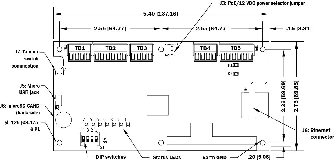
LNL-X2210 Hardware
LNL-X2210 Wiring
LNL-X2210 Connections | ||
|---|---|---|
TB1-1 | IN1 | Input 1 |
TB1-2 | IN1 | |
TB1-3 | IN2 | Input 2 |
TB1-4 | IN2 | |
TB2-1 | VO | Reader 1 Power Output – 12 VDC |
TB2-2 | LED | Reader 1 LED Output |
TB2-3 | BZR | Reader 1 Buzzer Output |
TB2-4 | CLK | Reader 1 CLK/Data 1/TR+ (B) * |
TB2-5 | DAT | Reader 1 DAT/Data 0/TR- (A) * |
TB2-6 | GND | Reader 1 Ground |
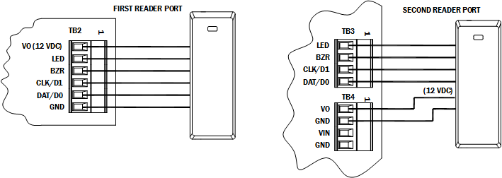
TB3-1 | LED | Reader 2 LED Output |
TB3-2 | BZR | Reader 2 Buzzer Output |
TB3-3 | CLK | Reader 2 CLK/Data 1 Input |
TB3-4 | DAT | Reader 2 DAT/Data 0 Input |
TB4-1 | VO | Auxiliary Power Output – 12 VDC |
TB4-2 | GND | Auxiliary Power Output Ground |
TB4-3 | VIN | Input Power – 12 VDC (from local power supply) |
TB4-4 | GND | Input Power Ground |
TB5-1 | NO | Relay K1 – Normally Open Contact |
TB5-2 | 1-C | Relay K1 – Common Contact |
TB5-3 | NC | Relay K1 – Normally Closed Contact |
TB5-4 | NO | Relay K2 – Normally Open Contact |
TB5-5 | 2-C | Relay K2 – Common Contact |
TB5-6 | NC | Relay K2 – Normally Closed Contact |
*Terms A & B are from the RS-485 standard.
Jumpers
Jumper | Set | Description |
|---|---|---|
J1 | N/A | Factory Use Only |
J2 | N/A | |
J3 | PoE | LNL-X2210 powered from the Ethernet connection |
12V | LNL-X2210 powered from an local 12 VDC power source connected to TB4-3 (VIN), | |
J4 | N/A | Factory Use Only |
J5 | N/A | Micro USB port (2.0) |
J6 | N/A | 10-Base-T/100Base-TX Ethernet Connection |
J7 | Cabinet Tamper Switch Input: short = tamper secure | |
J8 | N/A | microSD Card |
DIP Switches
The four switches on S1 DIP switch configure the operating mode of the LNL-X2210 processor. DIP switches are read on power-up except where noted.
1 | 2 | 3 | 4 | Definition |
|---|---|---|---|---|
OFF | OFF | OFF | OFF | Normal operating mode. |
ON | X | X | X | After initialization, enable default User Name (admin) and Password (password). The switch is read on the fly, no need to re-boot. For more information, refer to IT Security. |
OFF | ON | X | OFF | Use factory default communication parameters. |
ON | ON | X | OFF | Use Lenel default communication parameters. Contact system manufacturer for details. See Bulk Erase Configuration Memory. |
ON | ON | OFF | OFF | Bulk Erase prompt mode at power up. See Bulk Erase Configuration Memory. |
X | X | X | ON | Makes the LNL-X2210 report and function like an LNL-2210. To be used in situations where the host software has not been updated to support the LNL-X series product line. |
X = ON or OFF. All other switch settings are unassigned and reserved for future use.
Factory Default Communication Parameters
Interface 1 (NIC1)
- Network: static IP address: 192.168.0.251
- Subnet Mask: 255.255.0.0
- Default Gateway: 192.168.0.1
- DNS Server: 192.168.0.1
- Primary Host port: IP server, Data Security: TLS if Available, port 3001, communication address: 0
- Alternate Host Port: Disabled
Bulk Erase Configuration Memory
The bulk erase function can be used for the following purposes:
- Erase all configuration and cardholder database (sanitize board, less third party applications)
- Update OEM default parameters after OEM code has been changed
- Recover from database corruption causing LNL-X2210 board to continuously reboot
If clearing the memory does not correct the initialization problem, contact technical support.
Bulk Erase Steps
Important
Do not remove power during steps 1-6.
- Set S1 DIP switches to: 1 & 2 "ON," 3 & 4 "OFF."
- Apply power to the LNL-X2210 board. LED 1 on for about 15 seconds while LNL-X2210 boots up.
- After the LNL-X2210 boots up, watch for LEDs 1 & 2 and 3 & 4 to alternately flash at a 0.5 second rate.
- Within 10 seconds after the above pattern starts, change switches 1 or 2 to "OFF." If these switches are not changed, the LNL-X2210 board will power up using the OEM default communication parameters.
- LED 2 will flash indicating that the configuration memory is being erased. Full memory erase takes up to 60 seconds, usually a lot less. When complete, only LEDs 1 & 4 will flash for about 3 seconds.
- The LNL-X2210 board will complete its initialization in 2 seconds after LEDs 1 & 4 stop flashing.
Input Power
The LNL-X2210 is powered by one of two ways (jumper selected, J3):
- Power is supplied via the Ethernet connection using PoE or PoE+
- Or local 12 VDC power supply, TB4-3 (VIN), TB4-4 (GND)
Communication Wiring
The LNL-X2210 controller communicates to the host via the on-board 10-BaseT/100Base-TX Ethernet interface.
Reader/Serial I/O Device Wiring
Reader port 1 supports TTL (D1/D0, Clock/Data) or 2-wire RS-485 device(s). Reader port 2 supports TTL (D1/D0, Clock/Data). Power to reader port 1 is 12 VDC at 300 mA maximum. The reader connected to reader port 2 may be powered from the 12 VDC auxiliary power supply output; TB4-1 and TB4-2. Readers that require different voltage or have high current requirements should be powered separately. Refer to the reader manufacturer’s specifications for cabling requirements. In the 2-wire LED mode, the buzzer output is used to drive the second LED. Reader port configuration is set via the host software.
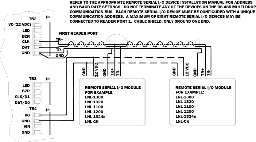
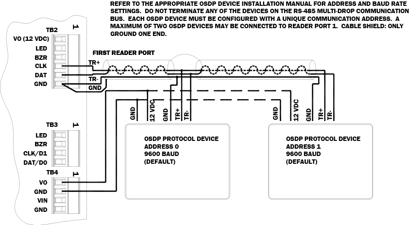
Reader port 1 can support up to eight 2-wire RS-485 remote serial I/O devices using MSP1 protocol or up to two OSDP devices. If two OSDP devices are used, reader port 2 will not support a third reader. If only one OSDP device is configured, then reader port 2 is available for a second reader. The maximum cable length is 2000 ft. (610 m). Do not terminate any RS-485 devices connected to reader port 1.
Notes
For OSDP cable lengths greater than 200 ft (61 m) or EMF interference, install 120Ω +/- 2Ω resistor across RS-485 termination ends.
Data 0 and Data 1 wires for Wiegand may be reused for OSDP. However, standard Wiegand cable may not meet RS-485 twisted pair recommendations. The reuse of cable works best on shorter cable lengths at lower data rates.
Important
Reader Wiring Diagrams
Typical Reader (OSDP Installation)
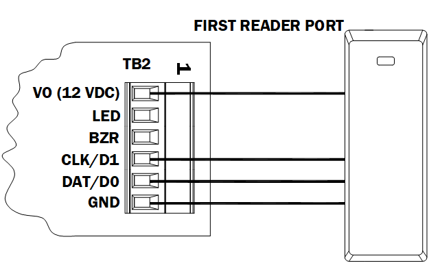
Typical D1/D0 or Clock/Data Reader Ports 1 and 2
Reader Port 1 Remote Serial I/O Devices using MSP1 Protocol (2-Wire RS-485)
Reader Port 1 OSDP Protocol Devices (2-Wire RS-485)
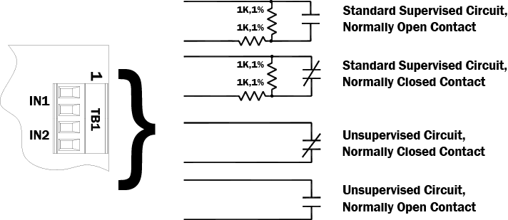
Input Circuit Wiring
Typically, these inputs are used to monitor door position, request to exit, or alarm contacts. Input circuits can be configured as unsupervised or supervised. When unsupervised, reporting consists of only the open or closed states.
When configured as supervised, the input circuit will report not only open and closed, but also open circuit, shorted, grounded, and foreign voltage. A supervised input circuit requires two resistors be added to the circuit to facilitate proper reporting. The standard supervised circuit requires 1k ohm, 1% resistors and should be located as close to the sensor as possible. Custom end of line (EOL) resistances may be configured via the host software.
The input circuit wiring configurations shown are supported but may not be typical:
Relay Circuit Wiring
Two Form-C contact relays are provided for controlling door lock mechanisms or alarm signaling devices. The relay contacts are rated at 2 A @ 30 VDC, dry contact configuration. Each relay has a Common pole (C), a Normally Open pole (NO) and a Normally Closed pole (NC). When you are controlling the delivery of power to the door strike, the Normally Open and Common poles are used. When momentarily removing power to unlock the door, as with a magnetic lock, the Normally Closed and Common poles are used. Check with local building codes for proper egress door installation.
Door lock mechanisms can generate EMF feedback to the relay circuit that can cause damage and premature failure of the relay plus affect the operation of the LNL-X2210. For this reason, it is recommended that either a diode or MOV (metal oxide varistor) be used to protect the relay. Wire should be of sufficient gauge to avoid voltage loss.
Caution
From the Auxiliary output, the LNL-X2210 can provide 12 VDC power for external devices provided that the maximum current is not exceeded. See the Specifications section for details.
Diode Selection
Diode current rating: 1x strike current. Diode breakdown voltage: 4x strike voltage. For 12 VDC or 24 VDC strike, diode 1N4002 (100V/1A) typical.
Memory Backup Battery
The SRAM is backed up by a rechargeable battery when input power is removed. This battery should retain the data for a minimum of 3 days. If data in the SRAM is determined to be corrupt after power up, all data, including flash memory, is considered invalid and is erased. All configuration data must be re-downloaded.
Note
The initial charge of the battery may take up to 48 hours to be fully charged.
IT Security
When installing the LNL-X2210, it is important to ensure that it is done in a secure manner.
Upon installation, the user accounts to the web configuration page should be created with secure passwords, and that all DIP switches are in the off position for the normal operating mode. The LNL-X2210 is shipped from the factory with a default login account, which is enabled when DIP 1 is moved from OFF to ON. The default login user name and password will be available for five minutes once enabled. Therefore, it is important that at least one user account is defined, and the DIP switches are set to OFF before the LNL-X2210 is commissioned. It is also highly recommended not to configure the LNL-X2210 with an IP address that is accessible from the public Internet.
To further enhance network security, options are available to disable SNMP, Zeroconf discovery, as well as the web configuration module itself. Additionally, data encryption can be enabled over the host communication port.
Status LEDs
Power-up: All LEDs OFF.
Initialization: After power is applied, LED 1 is ON for about 15 seconds, then LEDs 2 through 7 are flashed once at the beginning of initialization.
LEDs 5, 6 and 7 are turned ON for approximately 1 second after the hardware initialization has completed, then the application code is initialized. The amount of time the application takes to initialize depends on the size of the database, about 1 second without a card database. Each 10,000 cards adds about 2 seconds to the application initialization.
When LEDs 1 through 4 flash at the same time, data is being read from or written to flash memory; do not cycle power when in this state.
If the sequence stops or repeats, perform “Bulk Erase Steps” on page 3.
If clearing the memory does not correct the initialization problem, contact technical support.
Running: After initialization is complete, the LEDs have the following meanings:
LED | Description |
|---|---|
1 | Off-Line / On-Line: Off-Line = 20% ON, On-Line = 80% ON |
2 | Host Communication Activity |
3 | Readers (combined): |
4 | Input IN1 Status: OFF = Inactive, ON = Active, Flash = Fault * |
5 | Input IN2 Status: OFF = Inactive, ON = Active, Flash = Fault * |
6 | Cabinet Tamper |
7 | Reserved for Future Use |
D9 | Relay K1: ON = Energized |
D10 | Relay K2: ON = Energized |
YEL | Ethernet Speed: OFF = 10 Mb/S, ON = 100 Mb/S |
GR | OFF = No Link, ON = Good Link, Flashing = Ethernet Activity |
*If this input is defined, every three seconds the LED is pulsed to its opposite state for 0.1 seconds, otherwise, the LED is off.
Specifications
The interface is for use in low voltage, Class 2 circuits only.
The installation of this device must comply with all local fire and electrical codes.
- Primary Power: PoE (12.95 W), compliant to IEEE 802.3af or
PoE+ (25 W), compliant to IEEE 802.3at or
12 VDC ± 10%, 1.8 A maximum - Power Output: PoE: 12 VDC @ 625 mA including reader and Auxiliary Power output *
- Power Output: PoE+ or external 12 VDC: 12 VDC @ 1.25 A including reader and Auxiliary Power output *
- Micro USB Port: 5 VDC maximum (deduct 270 mA from reader and Auxiliary Power output)
* Excluding micro USB port
Caution
PoE power is to be supplied by an Access Control System Unit (ALVY), power limited, PoE+ injector or PoE+ Ethernet switch providing 42.5 – 57 VDC, 25.5W for maximum output.
- SRAM Backup Battery: Rechargeable battery
- microSD Card: Format: microSD or microSDHC; 2GB to 8GB.
- Host Communication: Ethernet: 10-BaseT/100Base-TX and Micro USB port (2.0) with optional adapter: pluggable model USB2-OTGE100
- Inputs: Two unsupervised/supervised, Programmable End of Line resistors, 1k/1k ohm, 1%, ¼ watt standard
One unsupervised input dedicated for cabinet tamper - Outputs: Two relays: Form-C contacts: 2 A @ 30 VDC, resistive
- Reader Interface:
- Power: 12 VDC ± 10%: PoE, PoE+ or local power supply, 300 mA maximum
- Data Inputs: Reader port 1: TTL compatible or 2-wire RS-485
Reader port 2: TTL compatible - LED Output: TTL compatible, high > 3 V, low < 0.5 V, 5 mA source/sink maximum
- Buzzer Output: Open collector, 12 VDC open circuit maximum, 40 mA sink maximum
- Cable Requirements:
- Power: 1 twisted pair, 18 AWG (when using local 12 VDC power supply)
- Ethernet: CAT-5, minimum
- Reader data (TTL): 6-conductor, 18 AWG, 500 ft. (152 m) maximum
- Reader data (RS-485): 1 twisted pair, shielded.
24 AWG, 120 ohm impedance,
2000 ft. (610 m) maximum - Alarm Input: 1 twisted pair per input, 30 ohm maximum
- Outputs: As required for the load
- Environmental:
- Temperature:
Storage: -55 to +85 °C (-67° to 185° F)
Operating: 0 to +70 °C (32° to 158° F) - Humidity: 5 to 95% RHNC
- Temperature:
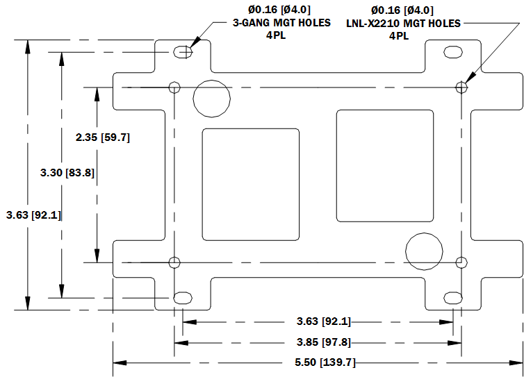
- Mechanical:
- Dimension: 5.5 in. (140 mm) W x 2.75 in. (70 mm) L x 0.96 in. (24 mm) H without bracket
5.5 in. (140 mm) W x 3.63 in. (92 mm) L x 1.33 in. (34 mm) H with bracket - Weight: 3.6 oz. (103 g) without bracket
4.43 oz. (125.5 g) with bracket
- Dimension: 5.5 in. (140 mm) W x 2.75 in. (70 mm) L x 0.96 in. (24 mm) H without bracket
These specifications are subject to change without notice.
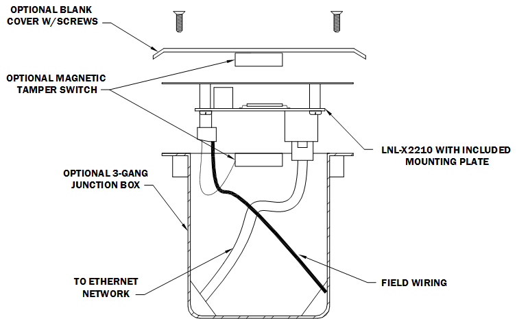
Additional Mounting Information
Sources for the optional items:
- 3-gang stainless steel blank cover. Available from: Leviton: part number 84033-40
Graybar: part number 88158404 - Magnetic switch set: G.R.I. part number: 505
Regulatory Information
FCC Compliance
This device complies with part 15 of the FCC Rules. Operation is subject to the following two conditions: (1) This device may not cause harmful interference, and (2) this device must accept any interference received, including interference that may cause undesired operation.
Liability
It is expressly understood and agreed that the interface should only be used to control exits from areas where an alternative method for exit is available. This product is not intended for, nor is rated for operation in life-critical control applications. LenelS2 is not liable under any circumstances for loss or damage caused by or partially caused by the misapplication or malfunction of the product. LenelS2’s liability does not extend beyond the purchase price of the product.
Certifications
For certification information, refer to the hardware documentation for the host application.
Product Warnings and Disclaimers
THESE PRODUCTS ARE INTENDED FOR SALE TO, AND INSTALLATION BY, AN EXPERIENCED SECURITY PROFESSIONAL. LENELS2 CANNOT PROVIDE ANY ASSURANCE THAT ANY PERSON OR ENTITY BUYING ITS PRODUCTS, INCLUDING ANY “AUTHORIZED DEALER”, IS PROPERLY TRAINED OR EXPERIENCED TO CORRECTLY INSTALL SECURITY RELATED PRODUCTS.
For more information on warranty disclaimers and product safety information, please check https://firesecurityproducts.com/en/policy/product-warning or scan the following code: