General
The LNL-X3300 intelligent controller provides decision-making, event reporting, and database storage for the Lenel hardware platform.
The LNL-X3300 communicates with the host via on-board 10-BaseT/100Base-TX Ethernet port or the Micro USB port (2.0) with an optional Micro USB to Ethernet adapter. Sub controllers are connected via ports 1 and 2 using 2-wire RS-485 multi-drop communication buses. The LNL-X3300 requires 12 to 24 VDC for power.
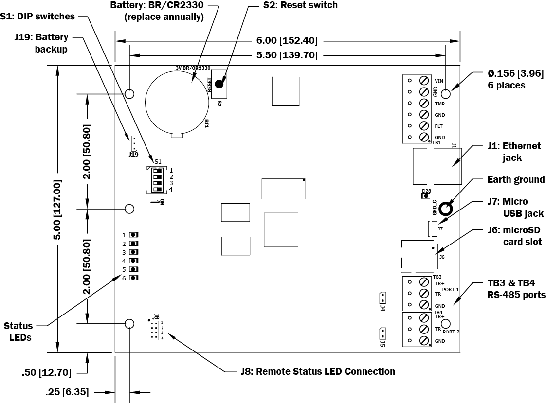
LNL-X3300 Hardware
LNL-X3300 Wiring and Setup
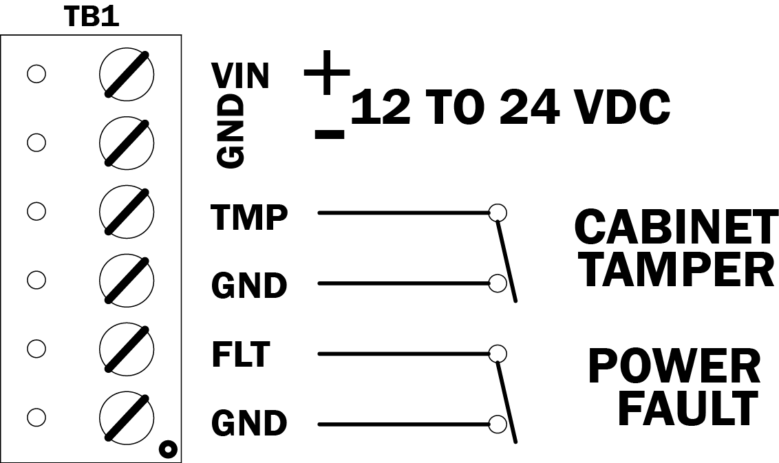
Connection | ||
|---|---|---|
TB1-1 | Power Fault Input | GND |
TB1-2 | FLT | |
TB1-3 | Cabinet Tamper Input | GND |
TB1-4 | FLT | |
TB1-5 | Power Input | GND |
TB1-6 | VIN: 12 to 24 VDC | |
TB2 | N/A | Not Used |
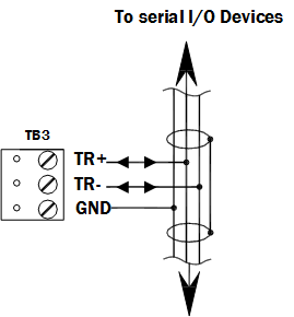
TB3-1 | SIO Port 1 (2-wire RS-485) | GND |
TB3-2 | TR- (B) * | |
TB3-3 | TR+ (A) * | |
TB4-1 | SIO Port 2 (2-wire RS-485) | GND |
TB4-2 | TR- (B) * | |
TB4-3 | TR+ (A) * | |
* Terms A & B are from the RS-485 standard.
Jumpers and Jacks
The LNL-X3300 controller hardware interface is configured using jumpers to set up the port interface and end of line termination.
Jumper | Set at | Description |
|---|---|---|
J1 | N/A | 10-Base-T/100Base-Tx Ethernet Connection (Port 0) |
J2 | N/A | Factory Use Only |
J3 | N/A | Factory Use Only |
J4 | OFF | Port 1 RS-485 EOL Terminator is Off |
ON | Port 1 RS-485 EOL Terminator is On | |
J5 | OFF | Port 2 RS-485 EOL Terminator is Off |
ON | Port 2 RS-485 EOL Terminator is On | |
J6 | N/A | microSD Card |
J7 | N/A | USB Port (2.0) |
J8-1 | N/A | Remote Status LED #1 * |
J8-2 | N/A | Remote Status LED #2 * |
J8-3 | N/A | Remote Status LED #3 * |
J8-4 | N/A | Remote Status LED #4 * |
J19 | OFF | Backup battery is OFF |
ON | Backup battery is ON. Refer to Memory and Real Time Clock Backup Battery. |
*Observe polarity connection to LED. External current limiting is not required.
DIP Switches
The four switches on S1 DIP switch configure the operating mode of the LNL-X3300 controller. DIP switches are read on power-up except where noted.
Pressing reset switch S2 causes the LNL-X3300 to reboot.
1 | 2 | 3 | 4 | Definition |
|---|---|---|---|---|
OFF | OFF | OFF | OFF | Normal operating mode. |
ON | X | OFF | OFF | After initialization, enable default User Name (admin) and Password (password). The switch is read on the fly, no need to reboot. For more information, refer to IT Security. |
OFF | ON | OFF | OFF | Use factory default communication parameters.* |
ON | ON | OFF | OFF | Use Lenel default communication parameters.* Contact system manufacturer for details. See Bulk Erase Configuration Memory. |
ON | ON | OFF | OFF | Bulk Erase prompt mode at power up. See Bulk Erase Configuration Memory. |
X | X | X | ON | Makes the LNL-X3300 report and function like an LNL-3300. To be used in situations where the host software has not been updated to support the LNL-X series product line. |
X = ON or OFF. All other switch settings are unassigned and reserved for future use.
* In the factory or Lenel default modes, downloaded configuration/database is not saved to flash memory.
Factory Default Communication Parameters
Interface 1 (NIC1)
- Network: static IP address: 192.168.0.251
- Subnet Mask: 255.255.0.0
- Default Gateway: 192.168.0.1
- DNS Server: 192.168.0.1
- Primary Host port: IP server, Data Security: TLS if Available, port 3001, communication address: 0
- Alternate Host Port: Disabled
Bulk Erase Configuration Memory
The bulk erase function can be used for the following purposes:
- Erase all configuration and cardholder database (sanitize board, less third party applications)
- Update OEM default parameters after OEM code has been changed
- Recover from database corruption causing LNL-X3300 board to continuously reboot
If clearing the memory does not correct the initialization problem, contact technical support.
Bulk Erase Steps
Important
Do not remove power during steps 1-6.
- Set S1 DIP switches to: 1 & 2 "ON," 3 & 4 "OFF."
- Apply power to the LNL-X3300 board. LED 1 on for about 15 seconds while LNL-X3300 boots up.
- After the LNL-X3300 boots up, watch for LEDs 1 & 2 and 3 & 4 to alternately flash at a 0.5 second rate.
- Within 10 seconds after the above pattern starts, change switches 1 or 2 to "OFF." If these switches are not changed, the LNL-X3300 board will power up using the OEM default communication parameters.
- LED 2 will flash indicating that the configuration memory is being erased. Full memory erase takes up to 60 seconds, usually a lot less. When complete, only LEDs 1 & 4 will flash for about 3 seconds.
- The LNL-X3300 board will complete its initialization in 2 seconds after LEDs 1 & 4 stop flashing.
Input Power, Cabinet Tamper, and UPS Fault Input Wiring
The LNL-X3300 requires 12 to 24 VDC power. Locate power source as close to the unit as possible. Connect power with minimum of 18 AWG wire.
Connect the GND signal to earth ground in ONE LOCATION within the system. Multiple earth ground connections may cause ground loop problems and is not advised.
Observe POLARITY on 12 to 24 VDC input.
There are two dedicated inputs for cabinet tamper and UPS fault monitoring. Normal (safe) condition is a closed contact. If these inputs are not used, install a jumper wire.
Communication Wiring
The LNL-X3300 controller communicates to the host via the on-board Ethernet 10-BaseT/100Base-TX port and/or the USB port (2.0) with an optional USB to Ethernet adapter.
Ports 1 and 2 utilize 2-wire RS-485 interface. The interface allows multi-drop communication on a single bus of up to 4,000 feet (1,219 m). Use 1-twisted pair, shielded, 120 ohm impedance, 24 AWG. 4,000 ft. (1,219 m) maximum cable length.
Port 1: 2-Wire RS-485
Port 2: 2-Wire RS-485

Important
Install the termination jumper ONLY on the panel at each end of the RS-485 bus. Failure to do so will compromise the proper operation of the communication channel.
Memory and Real Time Clock Backup Battery
The static RAM and the real time clock are backed up by a lithium battery when input power is removed. This battery should be replaced annually. If data in the static RAM is determined to be corrupt after power up, all data, including flash memory, is considered invalid and is erased. All configuration data must be re-downloaded.
During installation and while the unit is not powered, change the jumper (J19) position from OFF to ON to enable the battery backup.
Battery type: BR2330 or CR2330.
IT Security
When installing the LNL-X3300, it is important to ensure that it is done in a secure manner.
Upon installation, the user accounts to the web configuration page should be created with secure passwords, and that all DIP switches are in the off position for the normal operating mode. The LNL-X3300 is shipped from the factory with a default login account, which is enabled when DIP 1 is moved from OFF to ON. The default login user name and password will be available for five minutes once enabled. Therefore, it is important that at least one user account is defined, and the DIP switches are set to OFF before the LNL-X3300 is commissioned. It is also highly recommended not to configure the LNL-X3300 with an IP address that is accessible from the public Internet.
To further enhance network security, options are available to disable SNMP, Zeroconf discovery, as well as the web configuration module itself. Additionally, data encryption can be enabled over the host communication port.
Status LEDs
Power-up: All LEDs OFF.
Initialization: After power is applied or the reset switch is pressed, LED 1 is ON for about 15 seconds, then LEDs 2 through 6 are flashed once at the beginning of initialization.
LEDs 3 and 4 turn ON for approximately 1 second after the hardware initialization has completed, then the application code is initialized. The amount of time the application takes to initialize depends on the size of the database, about 1 second without a card database. Each 10,000 cards adds about 2 seconds to the application initialization.
When LEDs 1 through 4 flash at the same time, data is being read from or written to flash memory; do not cycle power when in this state.
If the sequence stops or repeats, perform Bulk Erase Steps.
Running: After initialization is complete, the LEDs have the following meanings:
LED | Description |
|---|---|
1 | Off-line / On-line and battery status |
Off-line = 20% ON, On-line = 80% ON | |
Double flash if battery is low | |
2 | Host communication activity (Ethernet) |
3 | Port 1 Communication Activity |
4 | Port 2 Communication Activity |
5 | Unassigned |
6 | Unassigned |
D28 | Ethernet Activity (Ethernet Port 0) |
YEL | On-board Ethernet Speed: OFF = 10 Mb/S, ON = 100 Mb/S |
GRN | OFF = No Link, ON = Good Link, Flashing = Ethernet Activity |
Specifications
The interface is for use in low voltage, Class 2 circuits only.
The installation of this device must comply with all local fire and electrical codes.
- Primary Power: 12 to 24 VDC ± 10%, 250 mA maximum (USB port current not included)
- Micro USB Port: 5 VDC, 500 mA maximum (add 270 mA to primary power current)
- Memory and Clock Backup Battery: 3 Volt Lithium, type BR2330 or CR2330
- microSD Card: Format: microSD or microSDHC; 2GB to 8GB
- Host Communication: Ethernet: 10-BaseT/100Base-TX and Micro USB port (2.0) with optional adapter: pluggable model USB2-OTGE100
- Serial I/O Device: Two each: 2-wire RS-485, 2,400 to 115,200 bps, asynchronous, half-duplex, 1 start bit, 8 data bits, and 1 stop bit
- Inputs: Two unsupervised dedicated for cabinet tamper and UPS fault monitoring
- Cable Requirements:
- Power: 1 twisted pair, 18 AWG
- Ethernet: CAT-5, minimum
- RS-485: 1 twisted pair, shielded, 120 ohm impedance, 24 AWG, 4,000 ft. (1,219 m) maximum cable length
- Environmental:
- Temperature:
Storage: -55 to +85 °C (-67° to 185° F)
Operating: 0 to +70 °C (32° to 158° F) - Humidity: 5 to 95% RHNC
- Temperature:
- Mechanical:
- Dimensions: 5 in. (127 mm) W x 6 in. (152.4 mm) L x 1 in. (25 mm) H
- Weight: 4.1 oz. (115 gm) nominal
These specifications are subject to change without notice.
Regulatory Information
FCC Compliance
This device complies with part 15 of the FCC Rules. Operation is subject to the following two conditions: (1) This device may not cause harmful interference, and (2) this device must accept any interference received, including interference that may cause undesired operation.
Liability
It is expressly understood and agreed that the interface should only be used to control exits from areas where an alternative method for exit is available. This product is not intended for, nor is rated for operation in life-critical control applications. LenelS2 is not liable under any circumstances for loss or damage caused by or partially caused by the misapplication or malfunction of the product. LenelS2’s liability does not extend beyond the purchase price of the product.
Certifications
For certification information, refer to the hardware documentation for the host application.
Product Warnings and Disclaimers
THESE PRODUCTS ARE INTENDED FOR SALE TO, AND INSTALLATION BY, AN EXPERIENCED SECURITY PROFESSIONAL. LENELS2 CANNOT PROVIDE ANY ASSURANCE THAT ANY PERSON OR ENTITY BUYING ITS PRODUCTS, INCLUDING ANY “AUTHORIZED DEALER”, IS PROPERLY TRAINED OR EXPERIENCED TO CORRECTLY INSTALL SECURITY RELATED PRODUCTS. FOR MORE INFORMATION ON PRODUCT WARNINGS AND DISCLAIMERS, SEE THE "LENELS2 PRODUCT WARNINGS AND DISCLAIMERS" KNOWLEDGE BASE ARTICLE IN THE LENELS2 KNOWLEDGE BASE. THIS INFORMATION IS SUBJECT TO CHANGE WITHOUT NOTICE.