Devices are installed on-premises to manage physical facilities. For more information about installing devices, refer to Hardware Installation Reference.
Viewing Devices
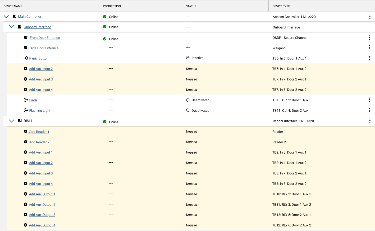
All the devices used to control or monitor spaces are configured and shown with their details on the Devices page.
The devices may be displayed in a Tree View (default) or List View. The Tree View displays all the devices in a hierarchy. The List View displays all the devices in a flat list. Use the buttons at the top of the page to toggle between the views. Once selected, the view will be saved as a user preference.
Selecting a device displays more detailed information and lists any recent events. To view more information about an event, select the device from the list to open its details screen. Select View All to navigate to the event feed and see filtered events associated with that device.
Search
When on the List View of the Devices page, a search can be performed to find a specific device by its name. In the Search field, start typing in the search term. The results will appear while typing (entering at least two characters will start the search). Search results may be limited based on the role of the user and site filters. Selecting a result displays the details for the device, including the device hierarchy.
Access Control
A gateway needs to be configured for the devices. An Elements video recorder (EVR) may also be used for access control devices.
Configure the Gateway's Devices
After the gateway or EVR is configured, add and configure the access control devices.
Repeat this procedure to add more devices.
When access controllers and reader interfaces are added, the system automatically includes available reader, input, and output slots for them based on the number of readers, inputs, and outputs supported.
Changing the number of readers, regardless of their online or offline status, may affect the system operating costs. Contact your VAR for more information.
Video
A video recorder needs to be configured before any other video devices are added.
After the recorder is configured, add cameras.
Device Statuses and Alerts
The Type column displays the name of the devices. Device icons indicate the device type:
Device type | |
|---|---|
Gateway | |
Video recorder | |
Access controller | |
Reader interface | |
Reader | |
Elevator reader | |
Reader auxiliary input | |
Reader auxiliary output | |
Camera | |
The Devices page shows live statuses. This is indicated by a Live icon at the top of the page.
Live status icons | |
|---|---|
 | Connected for status |
 | In the process of connecting for status |
Warning: Unable to connect. Refresh the page to see the latest status. | |
Connection icons indicate the communication status of each device:
Device connection status | |
|---|---|
Online - Connected to the device. When a device is online. Indicates when a “stateful” device, such as an OSDP reader, is online. (Stateful device status is also shown when these devices are in link mode, offline, or unable to communicate.) | |
Offline - Unable to connect to the device. When a device is offline, the status of all downstream devices will be shown as "Communication Error". When a gateway is offline, disconnected, or experiencing poor network conditions:
| |
Communication Error - Unable to communicate with the device. | |
Initializing - The device is performing an initialization process. Initialization occurs when a new gateway or recorder is installed, or after a gateway or recorder is deleted and then re-added. The initialization process takes about five minutes. | |
| |
Link Mode - The ODSP reader is attempting to establish an encrypted connection on the secure channel. | |
| |
| |
The ![]() (Issues) column will show a warning icon for devices that need attention. Mousing over the icon provides more information about the issue. Selecting the icon opens the device details screen.
(Issues) column will show a warning icon for devices that need attention. Mousing over the icon provides more information about the issue. Selecting the icon opens the device details screen.
Device alerts | |
|---|---|
Indicates some type of warning for a device. For example:
| |
Sites
Top-level devices, such as gateways and recorders, may be associated with sites. Their downstream devices will be included for the site assignment.
© 2026 Honeywell International Inc. All Rights Reserved.